Guide de démarrage rapide
Démarrage rapide/déballage
Nous vous souhaitons la bienvenue sur notre chaîne ! Cette vidéo est un guide sur la façon d'installer le système Larnitech rapidement et sans effort. L'installation se fera à l'aide d'une valise de démonstration. Un kit de formation comprend une valise de démonstration ① et une boîte contenant plusieurs articles supplémentaires ②.
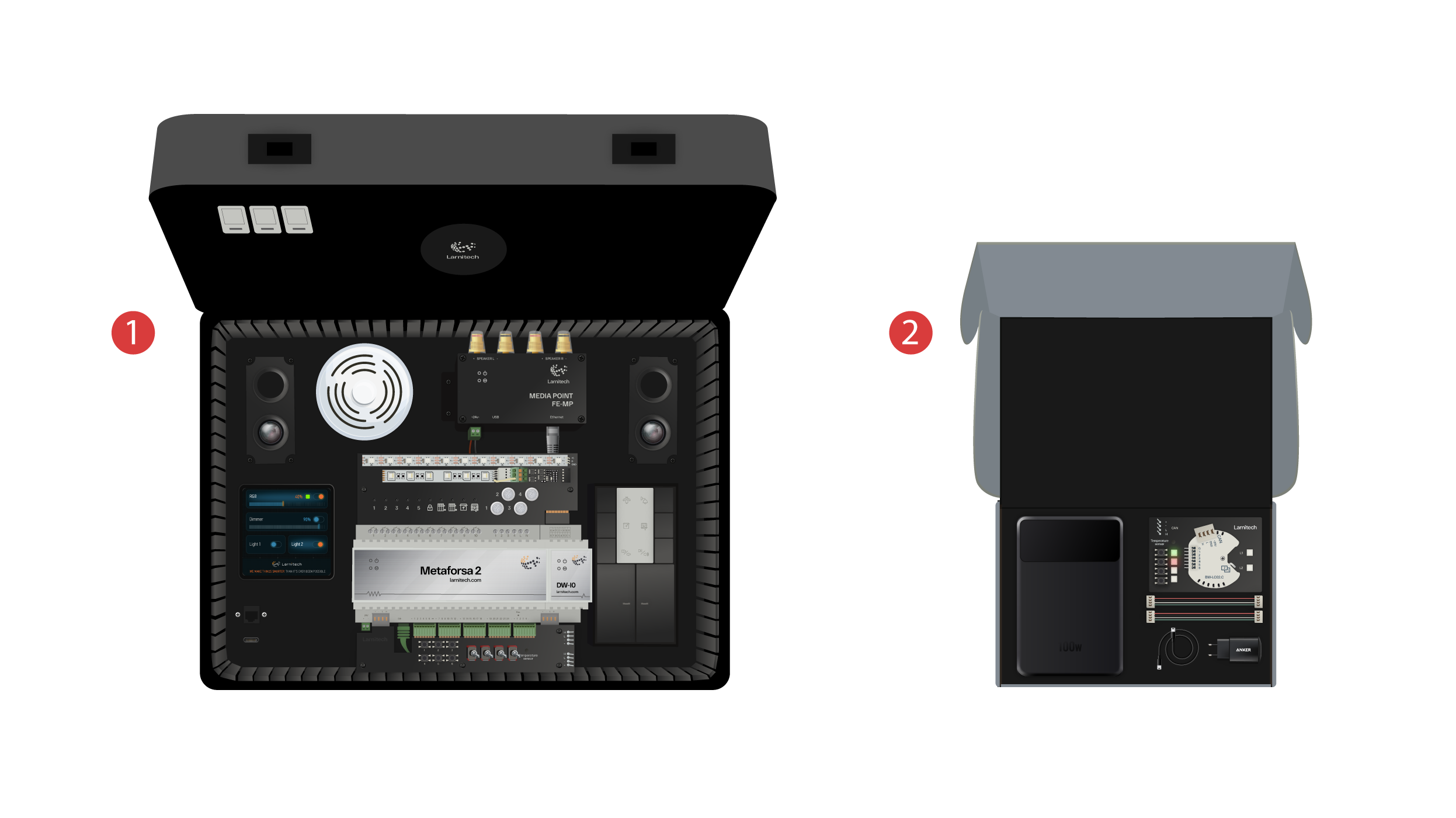
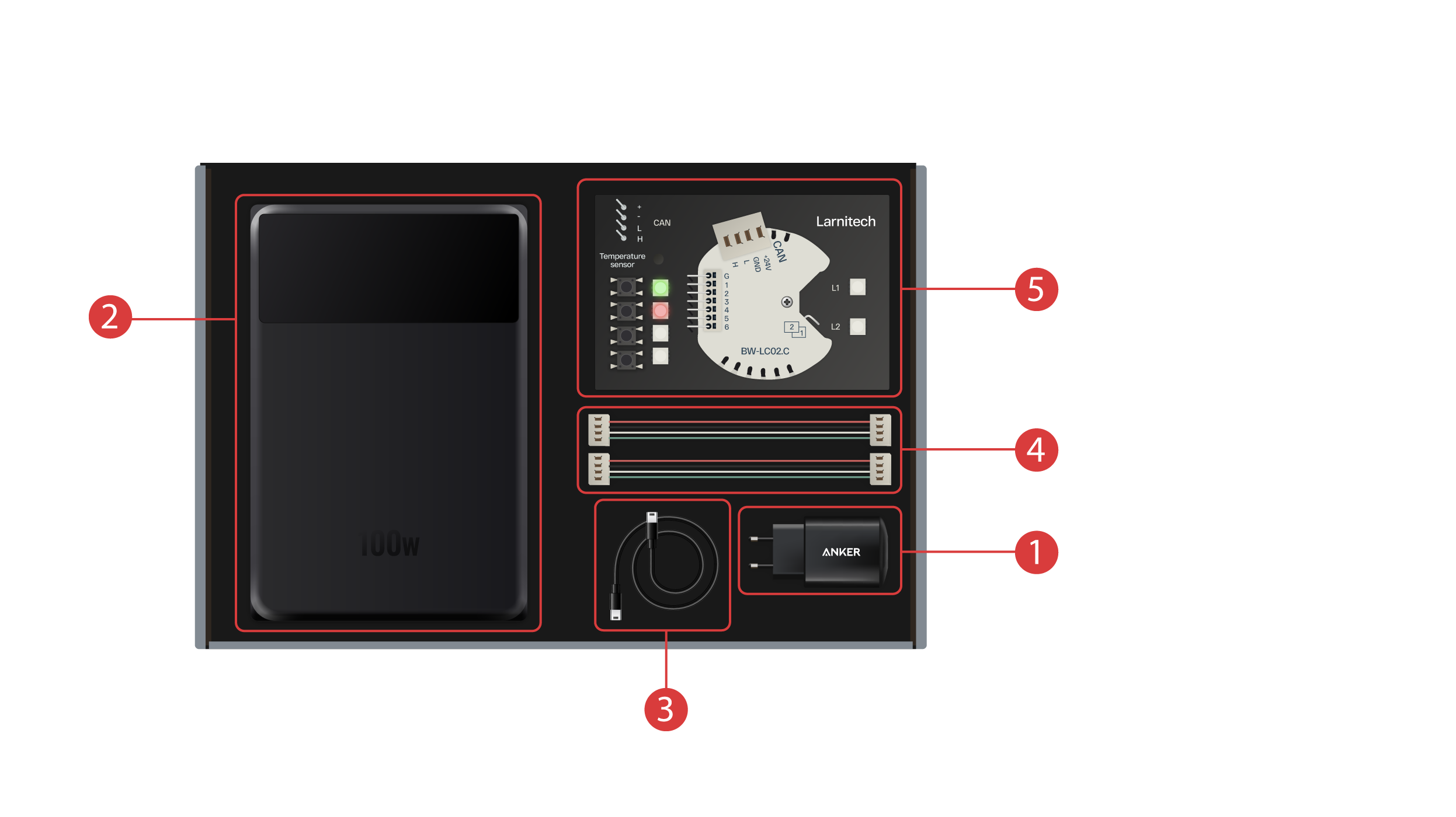
La boîte contient les éléments suivants :
① - Un bloc d'alimentation avec port USB de type C, prenant en charge la technologie Power Delivery ;
② - Une banque d'alimentation avec un écran et un port de sortie Type-C, qui peut être utilisée pour alimenter la valise de démonstration ;
③ - Un câble de type C avec un indicateur de consommation d'énergie ;
④ - 2 câbles de bus CAN ;
⑤ - Une carte de démonstration comprenant un module BW-LC02 avec 2 lumières LED, 4 boutons avec rétroéclairage et un capteur de température connecté.
La valise de démonstration contient les éléments suivants :
Le module "Metaforsa 2" comporte :
① - 10 canaux de relais auxquels sont connectés des voyants LED indiquant leur état actuel ;
② - 4 canaux dimmables, auxquels sont connectés des voyants LED dimmables ;
③ - 24 canaux d'entrée, auxquels sont connectés 6 boutons ④ et 4 interrupteurs ⑤ afin d'imiter différents capteurs ;
⑥ - Canaux d'entrée pour les capteurs de température avec un capteur connecté ;
⑦ - Bus CAN pour connecter des dispositifs supplémentaires. D'autres modules de la mallette de démonstration y sont connectés, ainsi que 2 ports ⑧ pour la connexion d'appareils externes ;
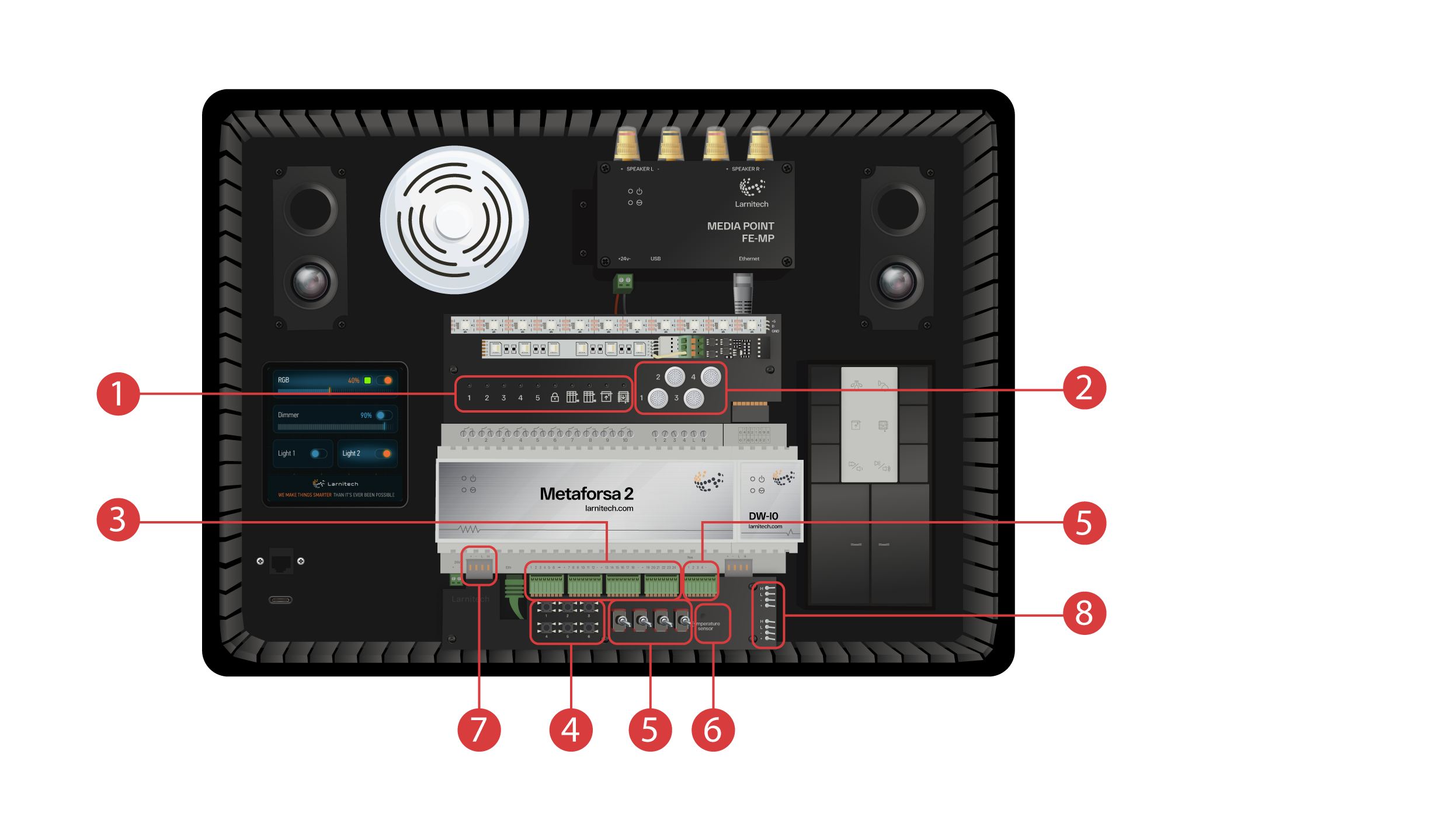
Module DW-IO
Ce module comporte 14 canaux d'entrée/sortie universels, auxquels sont connectés les éléments suivants :
① - Bande RGBW à 4 canaux, connectée via l'amplificateur de courant AMP5V-4 ② ;
③ - Une bande avec des lumières LED adressées. Chacune de ces LED peut briller avec sa propre couleur ;
④ - Un capteur de température ;
⑤ - And two buttons with backlight.
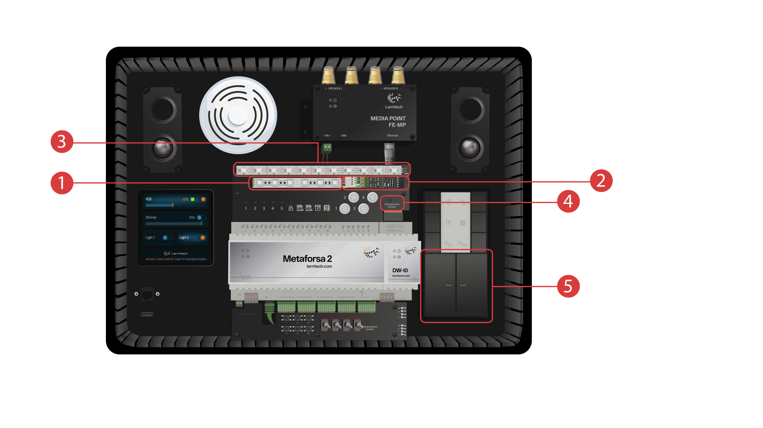
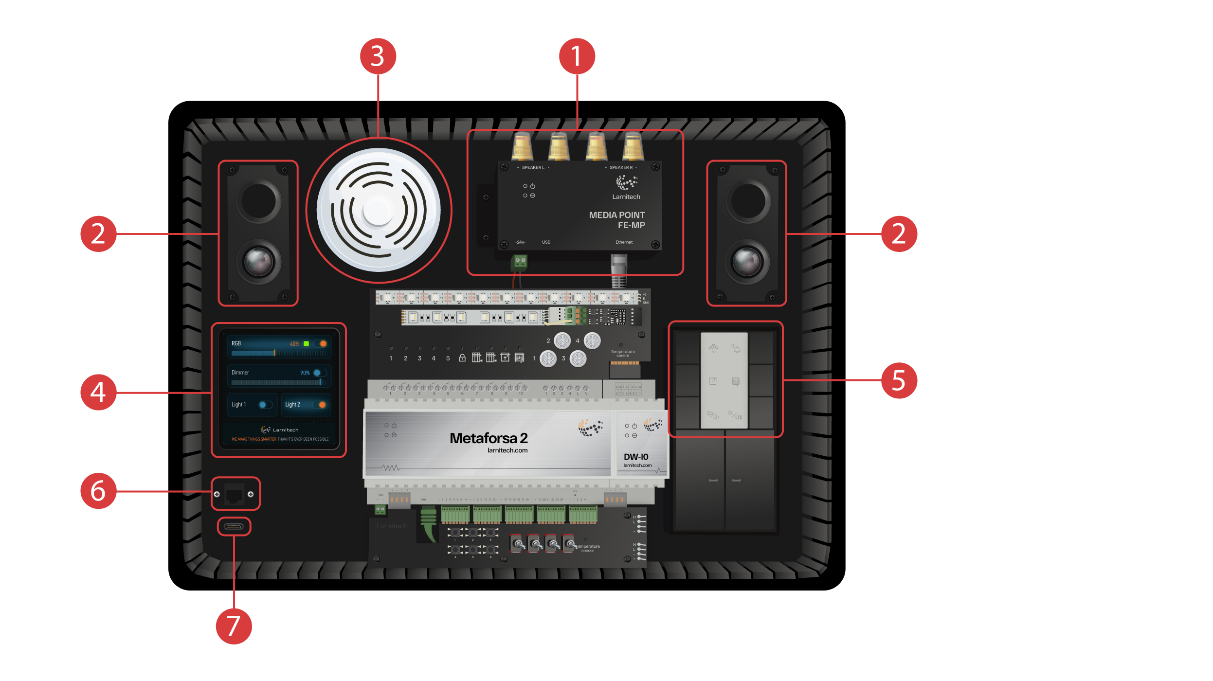
La mallette de démonstration présente également les caractéristiques suivantes:
① - Un Media Point FE-MP avec ② deux haut-parleurs ;
③ - Un capteur CW-CO2 six-en-un, qui mesure : Niveau du mouvement, L'éclairage, La température, Humidité de l'air, Niveau de CO2 et qui dispose d'un émetteur infrarouge.
④ - Un panneau de capteurs de 4 pouces LCP4 qui peut afficher soit une interface ordinaire, soit une interface adaptée aux panneaux muraux ;
À l'intérieur du boîtier se trouve un module de commande à boutons BW-SW24 auquel est connecté un clavier JUNG à six boutons de 24 volts ⑤.
Et un routeur Wi-Fi, qui peut se connecter à Internet soit via un port Ethernet ⑥ sur le panneau avant du boîtier, soit via un réseau Wi-Fi disponible.
Pour l'alimentation électrique, il y a un port Type-C ⑦, qui se trouve sur le panneau avant.
Tout le matériel installé dans la valise de démonstration est alimenté en 20 volts, ce qui est absolument sans danger pour l'utilisateur.
Branchez le câble d'alimentation et le câble Ethernet. Si vous n'avez pas la possibilité de vous connecter via Ethernet, nous vous montrerons plus loin dans cette vidéo comment connecter le routeur intégré à votre réseau Wi-Fi.
Pour continuer, l'application Larnitech doit être installée sur votre smartphone ou votre tablette. Il vous suffit de scanner le premier code QR sur le dessus de votre valise.
Si après avoir installé et démarré l'application, la connexion ne s'établit pas automatiquement, vous devrez vous connecter au réseau Wi-Fi 'Larnitech_case_5G' à l'aide de votre appareil mobile. Lancez ensuite l'application et scannez le premier code QR dans la section 'Connexions'.
Il se peut que vous deviez désactiver la transmission de données sur votre appareil mobile si le kit de démonstration n'est pas connecté à l'internet.

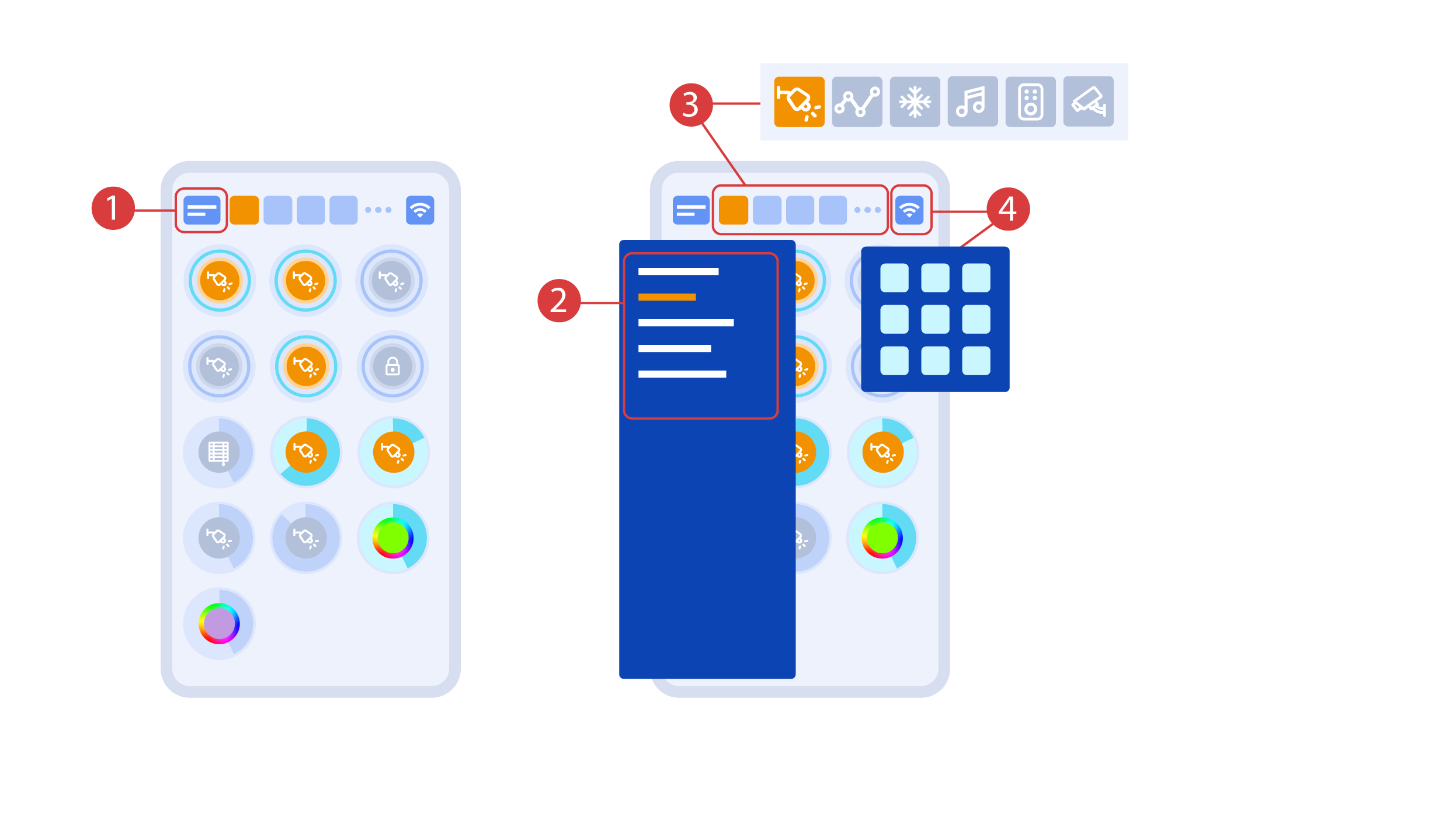
The main screen of the app has several key elements. In the upper left corner there is the ‘area select’ menu ①.
Just click one of the available areas in order to manage it ②.
Then there are icons which let you choose the executors, sensors, climate, multimedia, remote controls and cameras ③. In the right corner there is an icon for the additional menu ④. Inside the icon you can also see the status of the current connection.
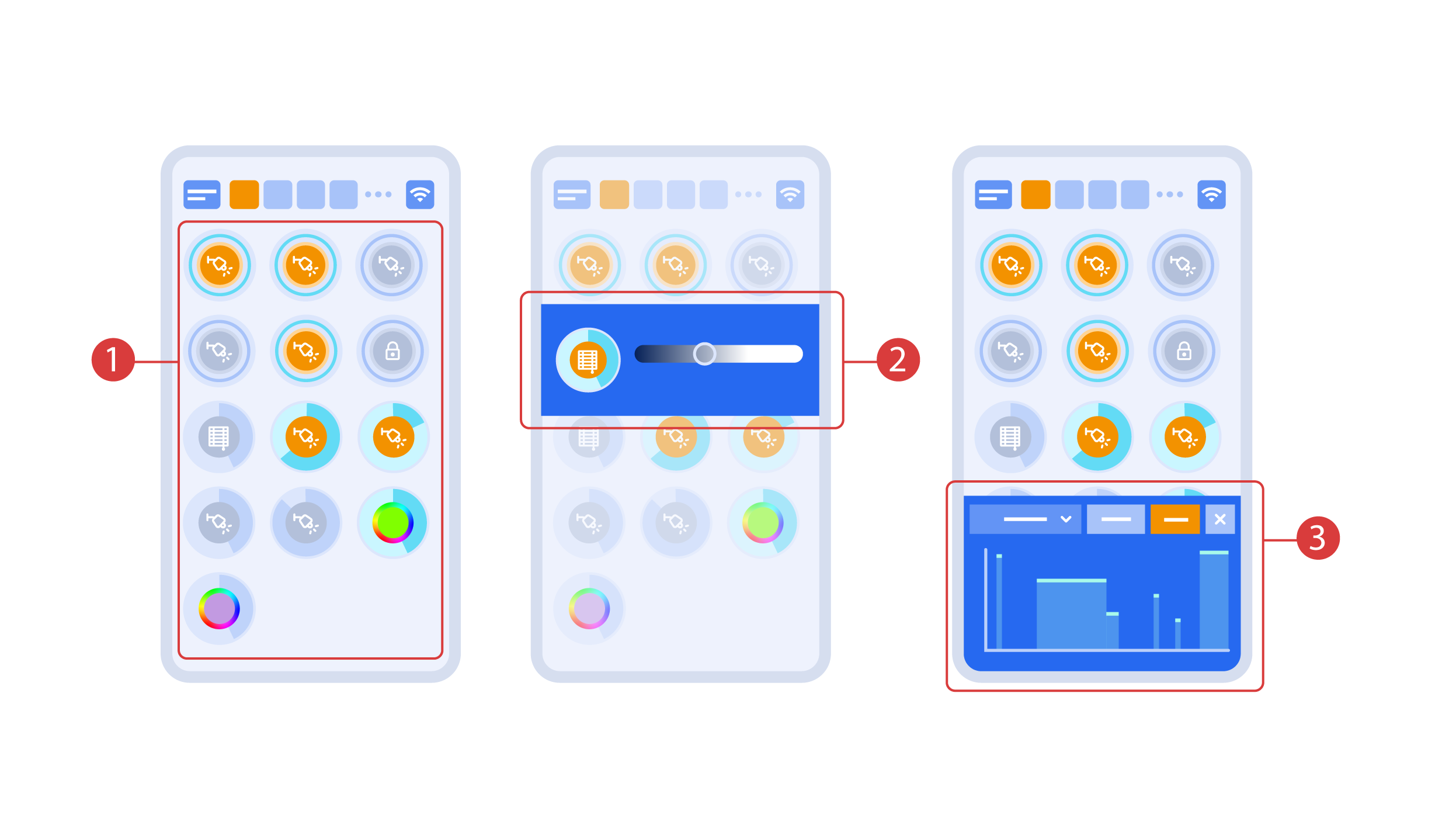
Turning the executors ① on or off is done with a simple click. In order to change the level of lighting ②, color of lights or the position of the blinds, use a double click. In order to access the status history ③ of this executor or sensor, press and hold the icon for one second.
A short press of the physical buttons on the panel turns the light on or off. Press and hold the button to change the light brightness.
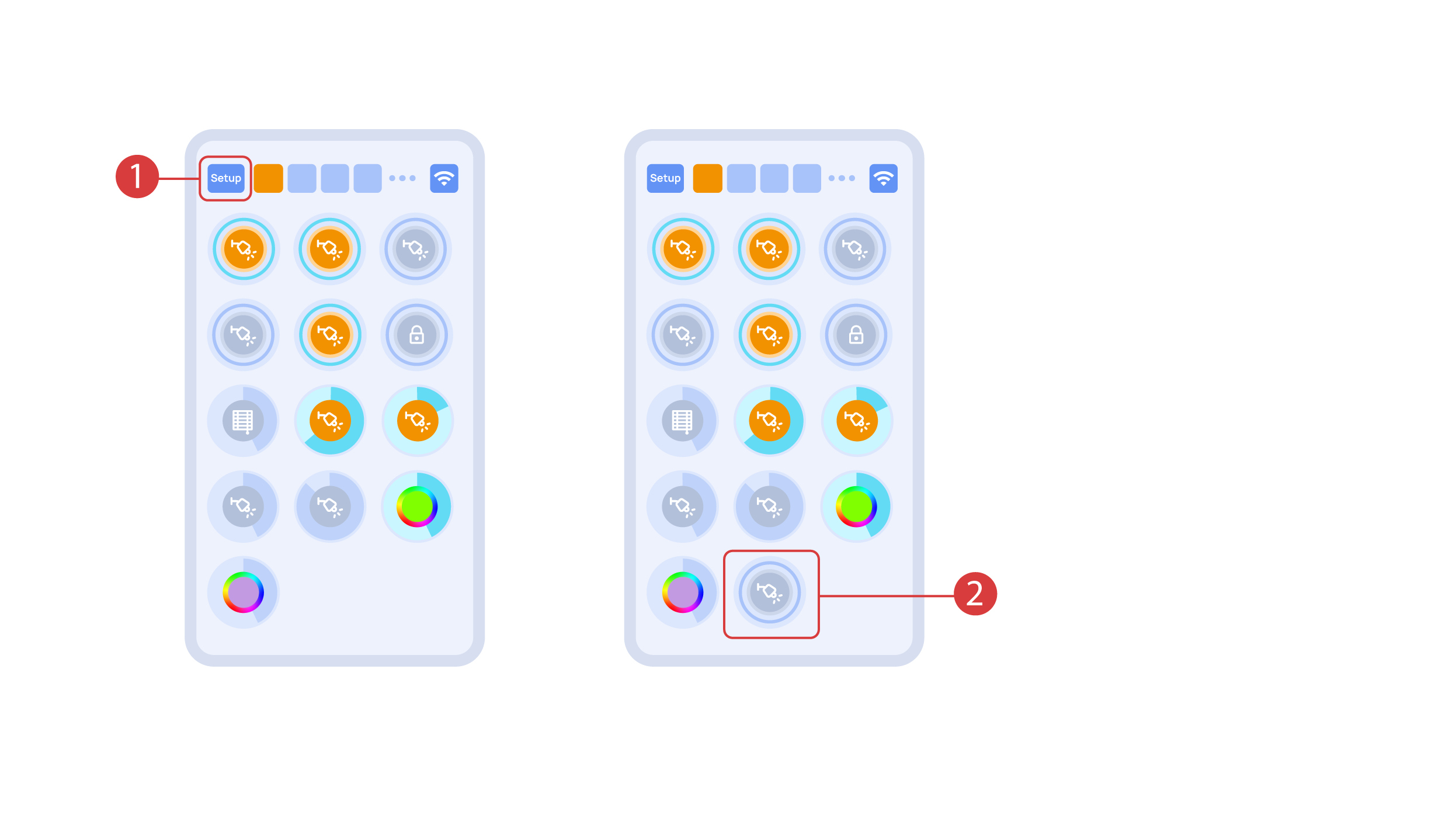
In order to demonstrate the Plug and Play function, we open the executors in the Setup area ① and connect the module to the CAN bus. The system automatically detects the new module and adds it to the ‘Setup’ area, ② where we are able to control the new module instantly.
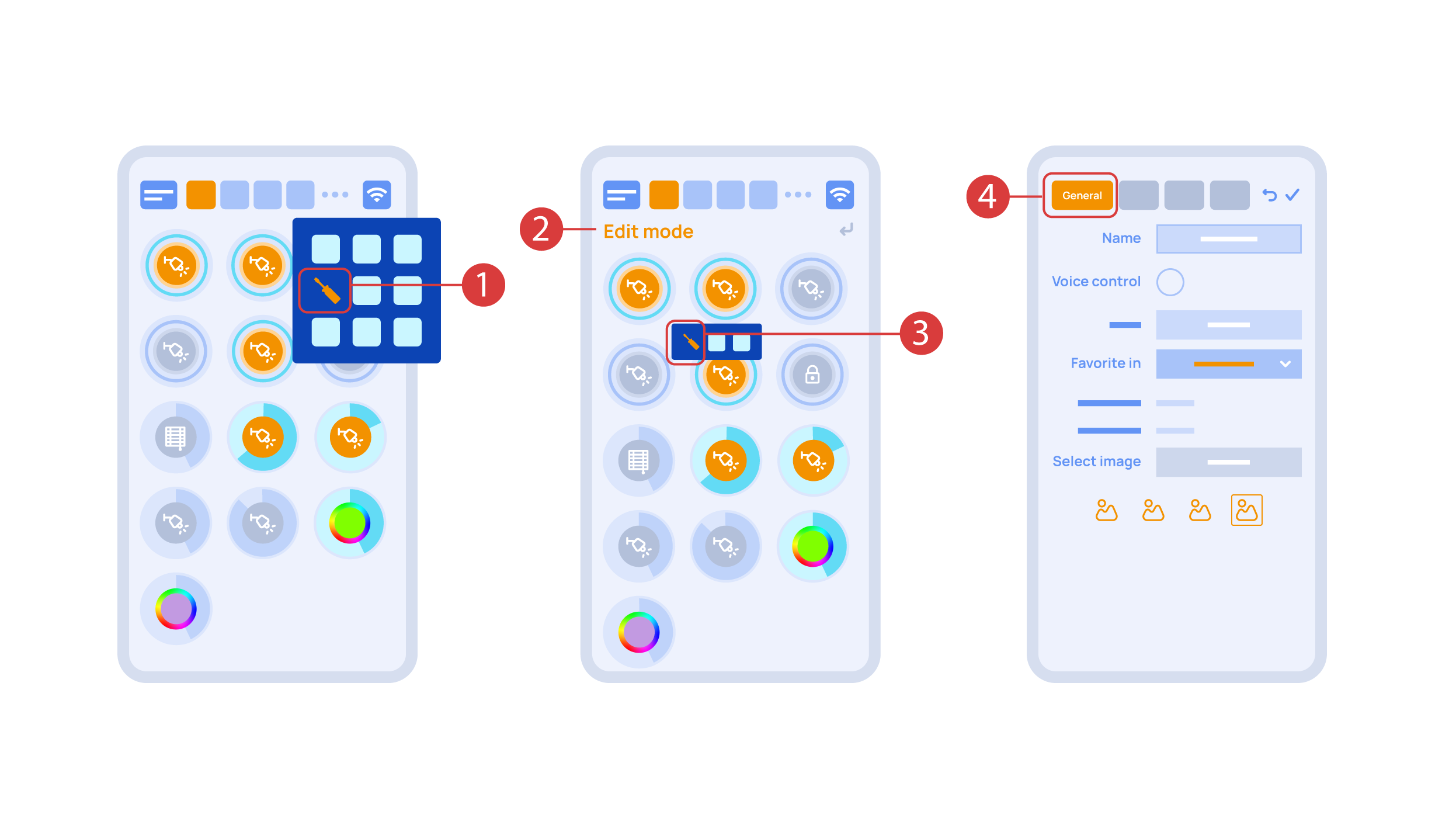
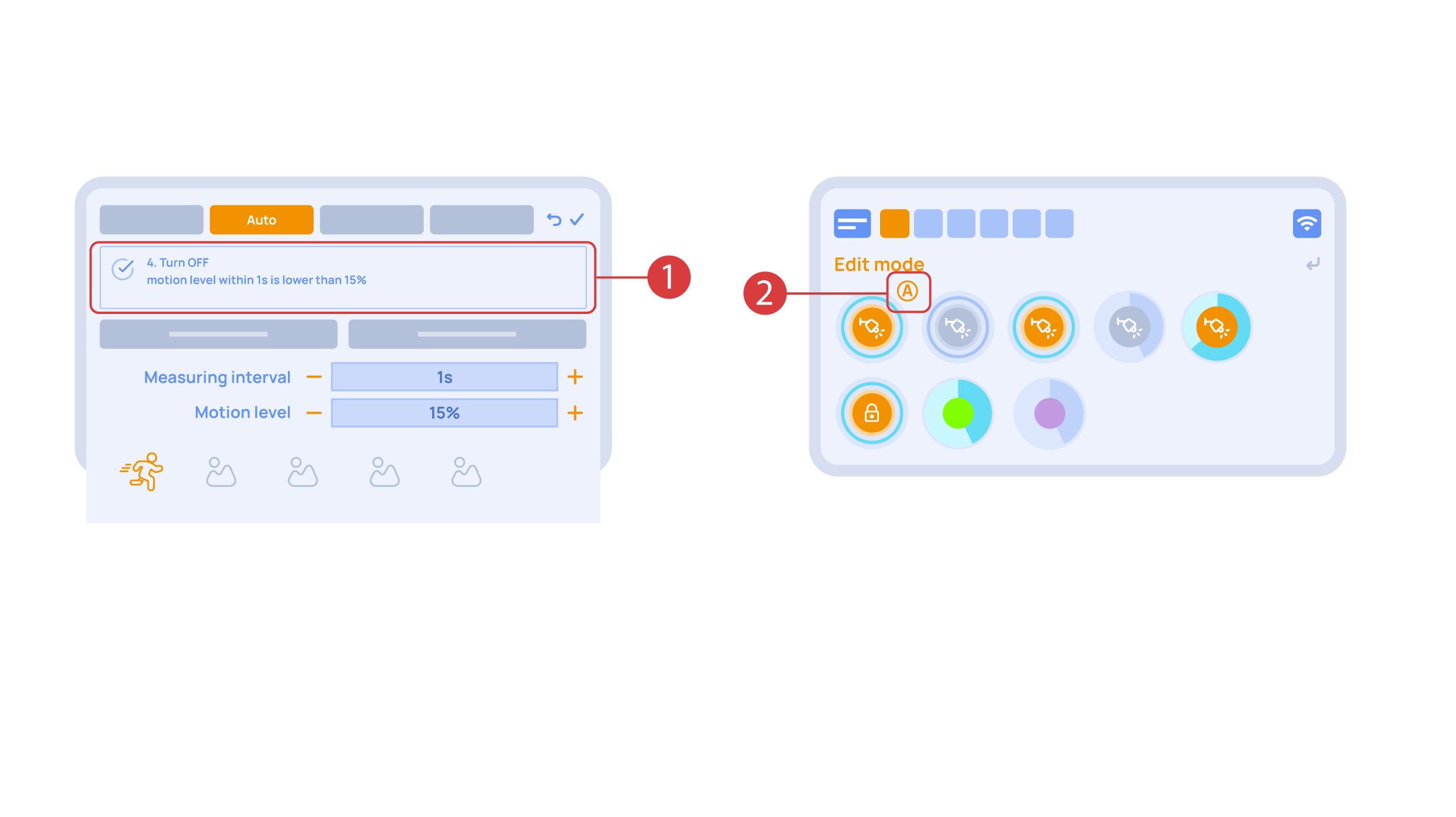
Now we can set up these executors. In order to do this, enter the additional menu ① and activate the edit mode, by pressing the appropriate icon .
Now we are in the edit mode ②, which can be seen from the appropriate notification in the top part of the screen. In this mode, when we press and hold an icon, we can move it among other elements and place it into another Room by placing it in the Area-choosing Menu and then choosing the area that we need. A long press ③ of the element starts the menu, from which we set up the current element.In the ‘General’ ④ section we can change the name of the element, add a voice command for it, change an icon or add the element to ‘Favorites’.
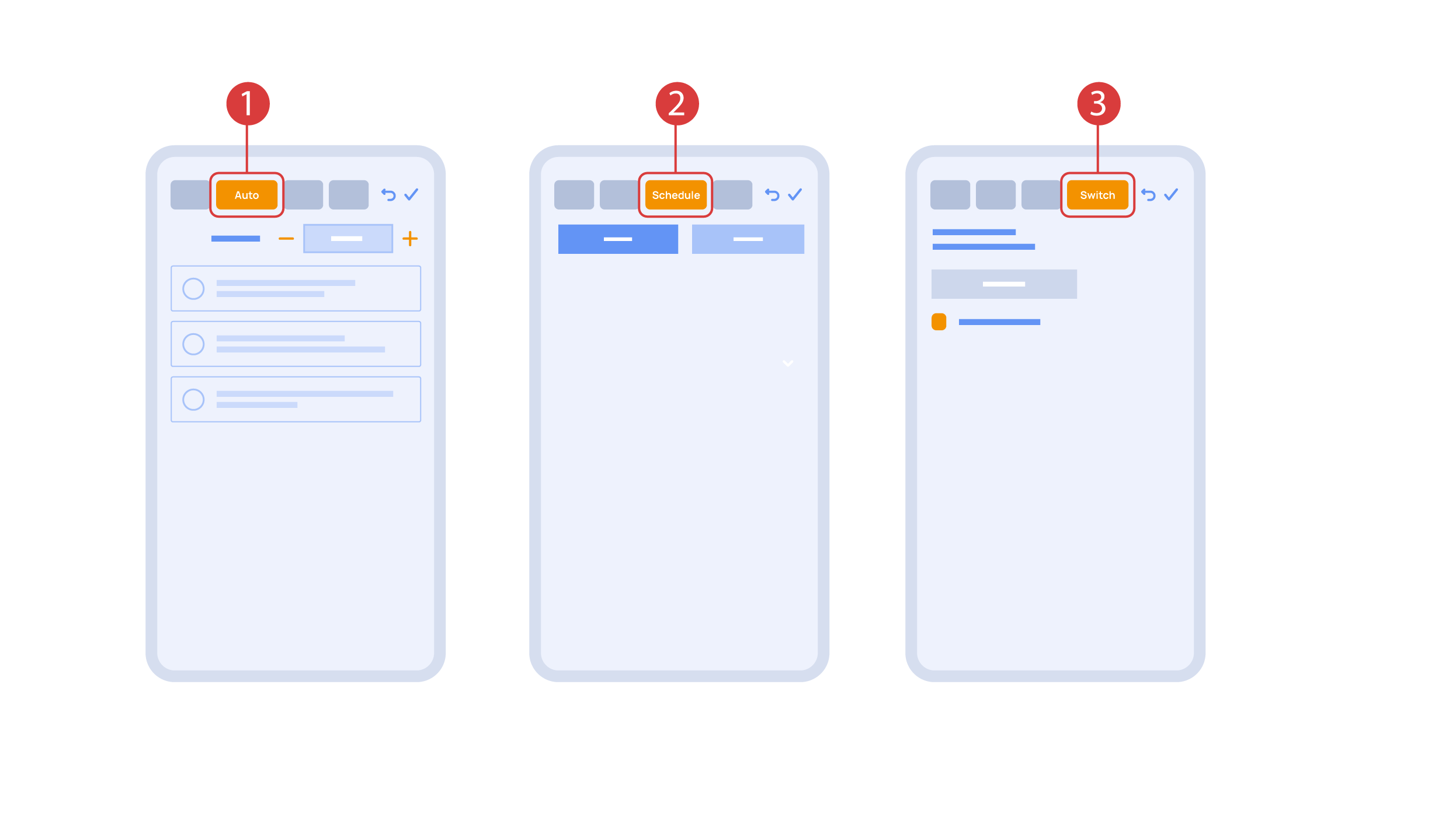
‘Auto’ section ① lets us activate the automation with a few clicks, as well as set up its parameters.
In the ‘schedule’ section ②, you can determine the schedule when the given element will turn on or off, including by using the time of the setting and rising of the sun.
The ‘Switches’ tab ③ lets you bind a button to control the executor.
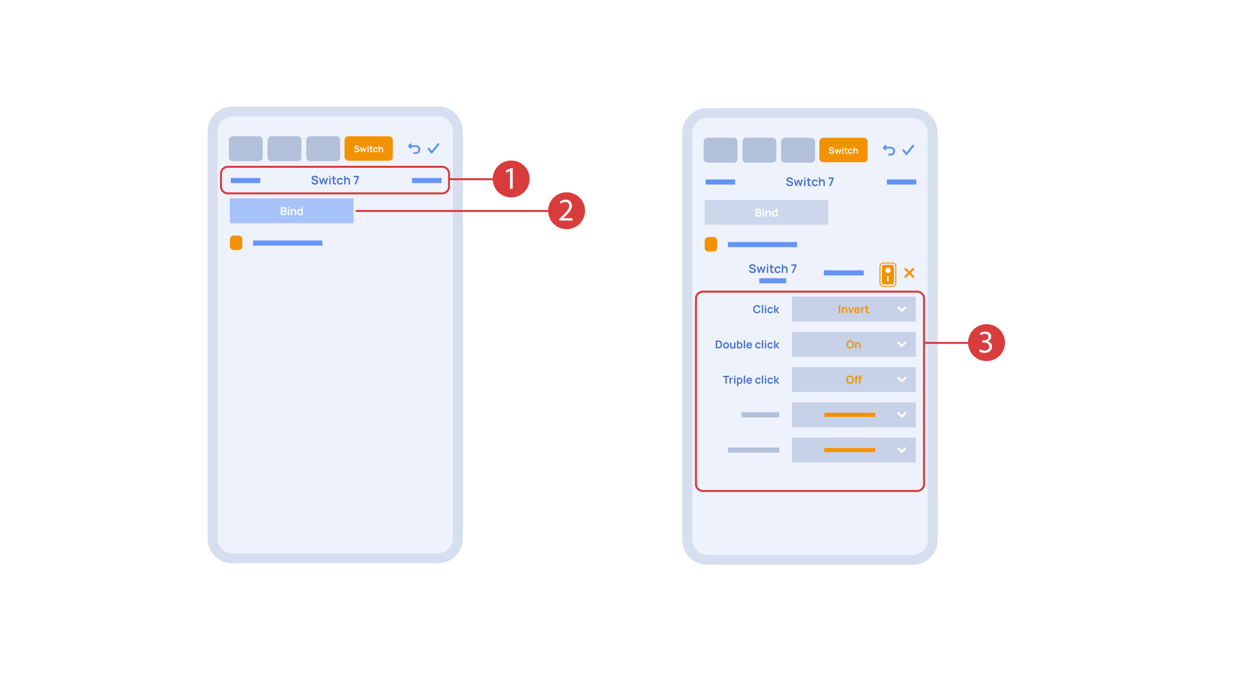
In order to do this, ① we press the button we need to bind. The system displays it, after which we press ‘Bind’② and save the changes. Now this button controls the executor
The ‘Switches’ tab ③ also features additional button setup options. For example, we can program the executor to be controlled with a double or triple click of a button, as well as define an action performed by this, for example ‘only turning on’ or ‘only turning off’ an executor. In this case we are setting up the button to do the following: one click will cause the lamp to toggle, a double click will turn it on and a triple click will turn it off. In this way a single button can perform up to five different actions.
Let’s also set up basic automation of turning an executor on or off with the help of a motion sensor.
The ‘Auto period’ ① option sets the time for which the automation is disabled after an executor is manually controlled.For our demonstration purposes, we will set it to zero.
Then we will activate the automation ② to turn on the executor when motion is detected. We choose the motion sensor ③ and the level of motion ④. We can also choose a light sensor and its parameters.
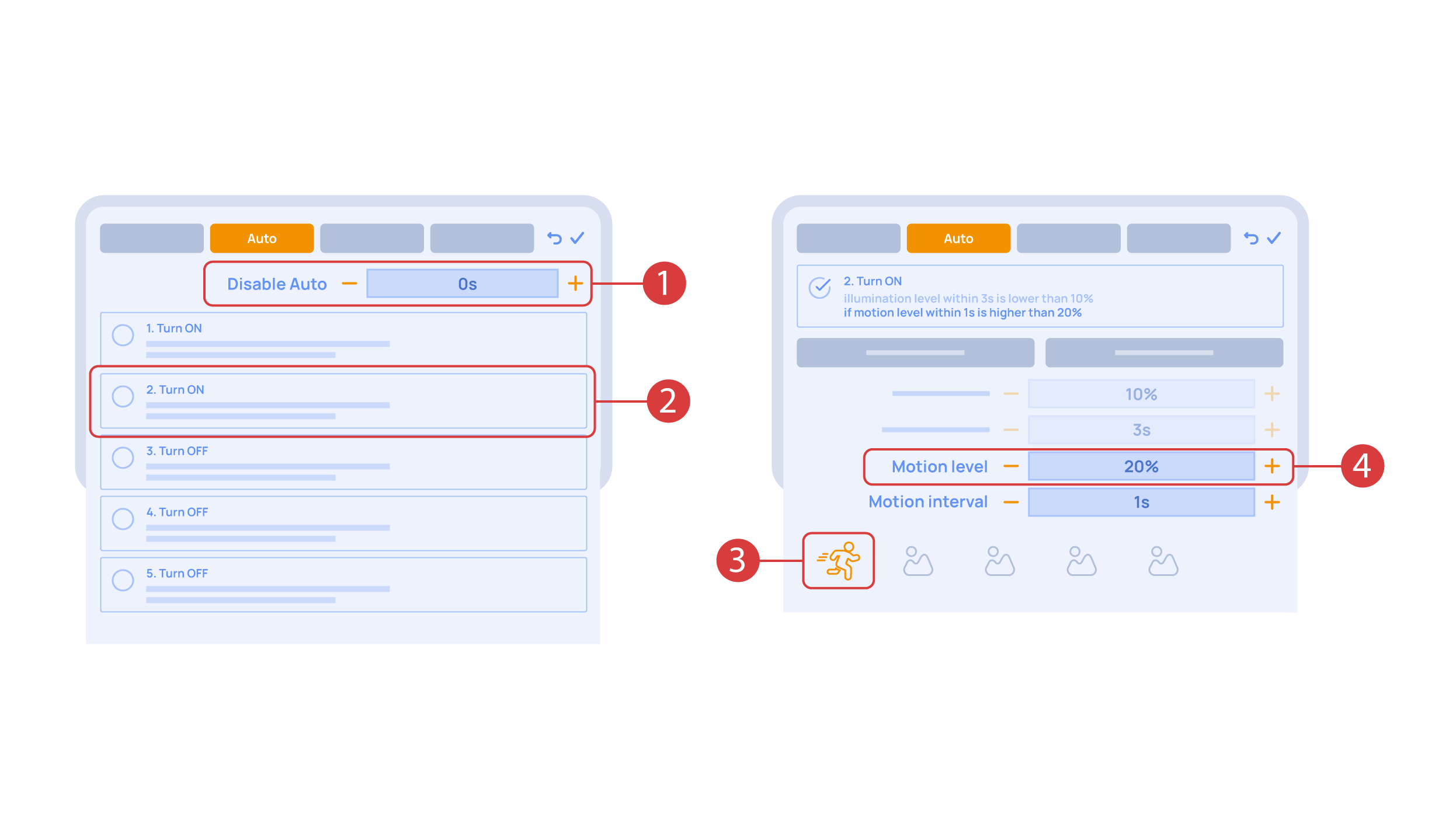
Now we will activate turning off ① of an executor if there is no motion: we choose the same sensor, set a lower threshold and a minimal time.Save the changes.
The extra ‘A’ icon ② will be added to the executor icon, meaning that automation has been set up for it. Now the lamp will be turned on when motion is detected and instantly turned off when no motion is detected.
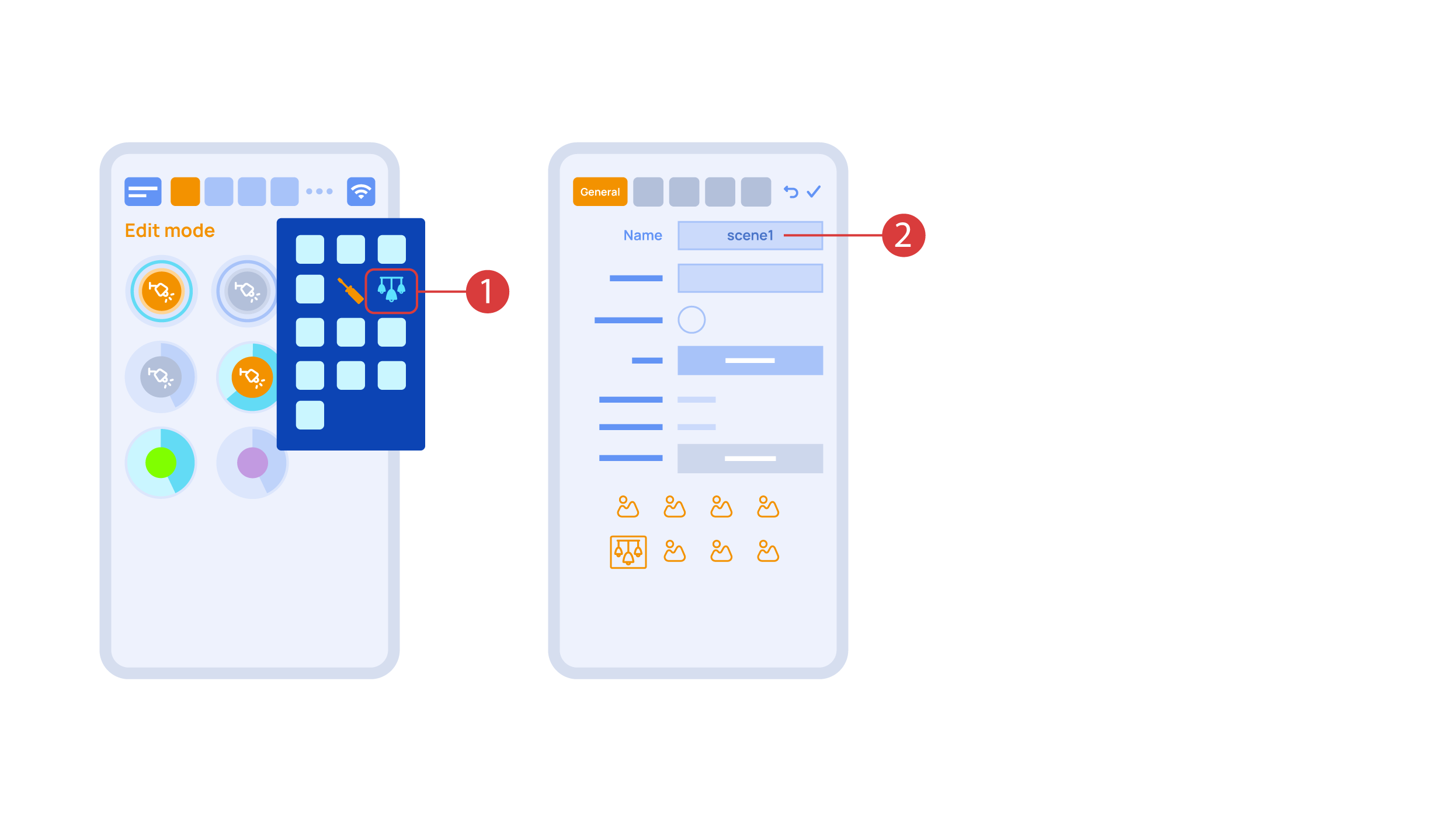
Let’s create a light scheme. For this we need to select the appropriate item in the additional menu ①. Give the light scheme a name ②.
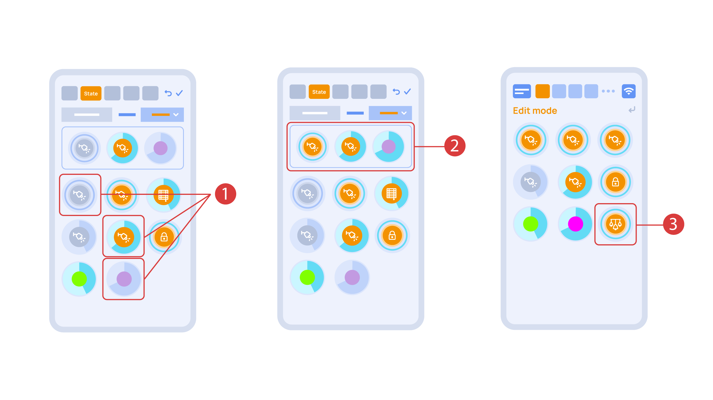
In the ‘State’ tab, use a long press to add the lights we want to use into the light scene ① and set up their state ②. ‘Auto’, ‘Schedule’, ‘Switch’ tabs are the same for all the executors.
Save the changes and we are able to use the newly-created light scheme ③ immediately.
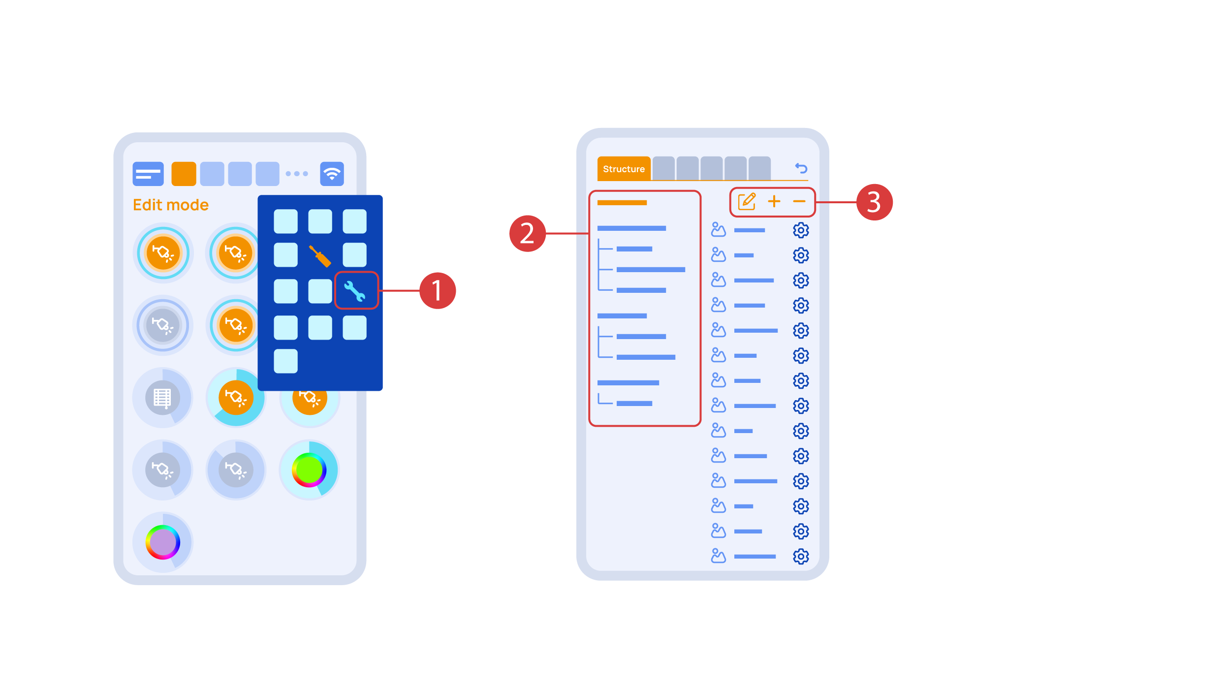
While you are in the Edit Mode, there is a ‘Setup’ ① icon in the additional menu.
Here in the ‘Structure’② tab we can see all the areas.
We can create new ones ④, rename them and move the elements around.
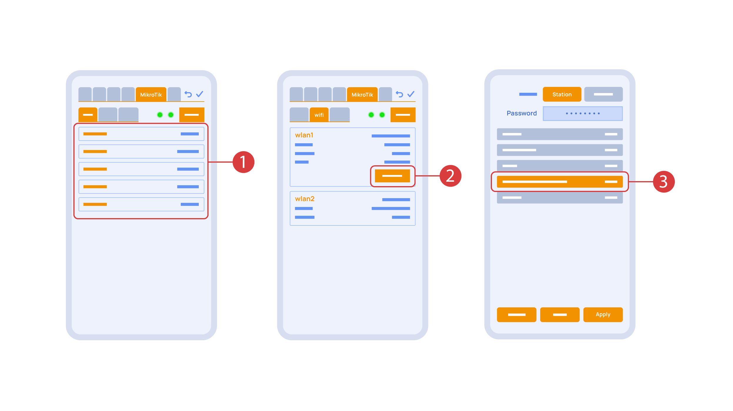
In the ‘Mikrotik’ tab ① you can see the current parameters of your router, which you can also connect to your local Wi-Fi network.
In order to do this, enter the Wi-Fi sub-menu, click the wlan1 interface configuration ②, after which choose the ‘station’ mode, choose a Wi-Fi network out of the list ③ of available ones and enter the connection password.
In the ‘Backups’ tab ① you can see the list of saved configurations, which can be restored if necessary.

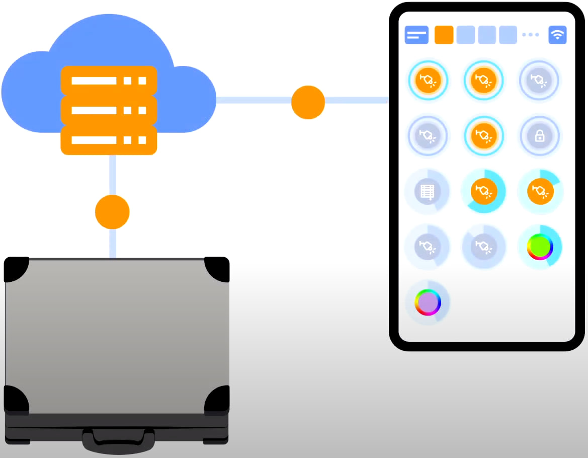
For cloud access to the device, you do not need any extra settings. The app detects the absence of the system in your local network and automatically establishes the connection via the cloud.
We thank you for watching this tutorial! If you have questions or need extra help, please do not hesitate to refer to our technical support team. See you in the next episodes!