Difference between revisions of "Quick Start Guide/it"
(Created page with "Se dopo l'installazione e l'avvio dell'app la connessione non viene stabilita automaticamente, è necessario collegarsi alla rete Wi-Fi "Larnitech_case_5G" con l'aiuto del pro...") |
(Created page with "La schermata principale dell'app presenta diversi elementi chiave. Nell'angolo in alto a sinistra si trova il menu "Seleziona area" <span style="font-size: 30px; vertical-alig...") |
||
| Line 74: | Line 74: | ||
<hr> | <hr> | ||
| − | + | La schermata principale dell'app presenta diversi elementi chiave. Nell'angolo in alto a sinistra si trova il menu "Seleziona area" <span style="font-size: 30px; vertical-align: middle;">①</span>. | |
| − | + | Basta fare clic su una delle aree disponibili per avviare la gestione di essa <span style="font-size: 30px; vertical-align: middle;">②</span>. | |
| − | + | Ci sono anche delle icone che permettono di selezionare gli esecutori, i sensori, il meteo, i file multimedia, i telecomandi e le telecamere <span style="font-size: 30px; vertical-align: middle;">③</span>. Sull'angolo destro è presente un'icona per il menu aggiuntivo <span style="font-size: 30px; vertical-align: middle;">④</span>. All'interno dell'icona è possibile visualizzare anche lo stato della connessione attuale. | |
[[File:DemoCase7.png|1000x800px]] | [[File:DemoCase7.png|1000x800px]] | ||
<hr> | <hr> | ||
Revision as of 15:25, 2 November 2023
Avvio rapido/unboxing.
Vi diamo il benvenuto nel nostro canale! Questo video è una guida su come configurare il sistema Larnitech in modo rapido e semplice. La configurazione verrà effettuata con l'aiuto di una valigetta dimostrativa. Il kit esplicativo comprende una valigetta dimostrativa ① e una scatola con diversi componenti aggiuntivi ②.
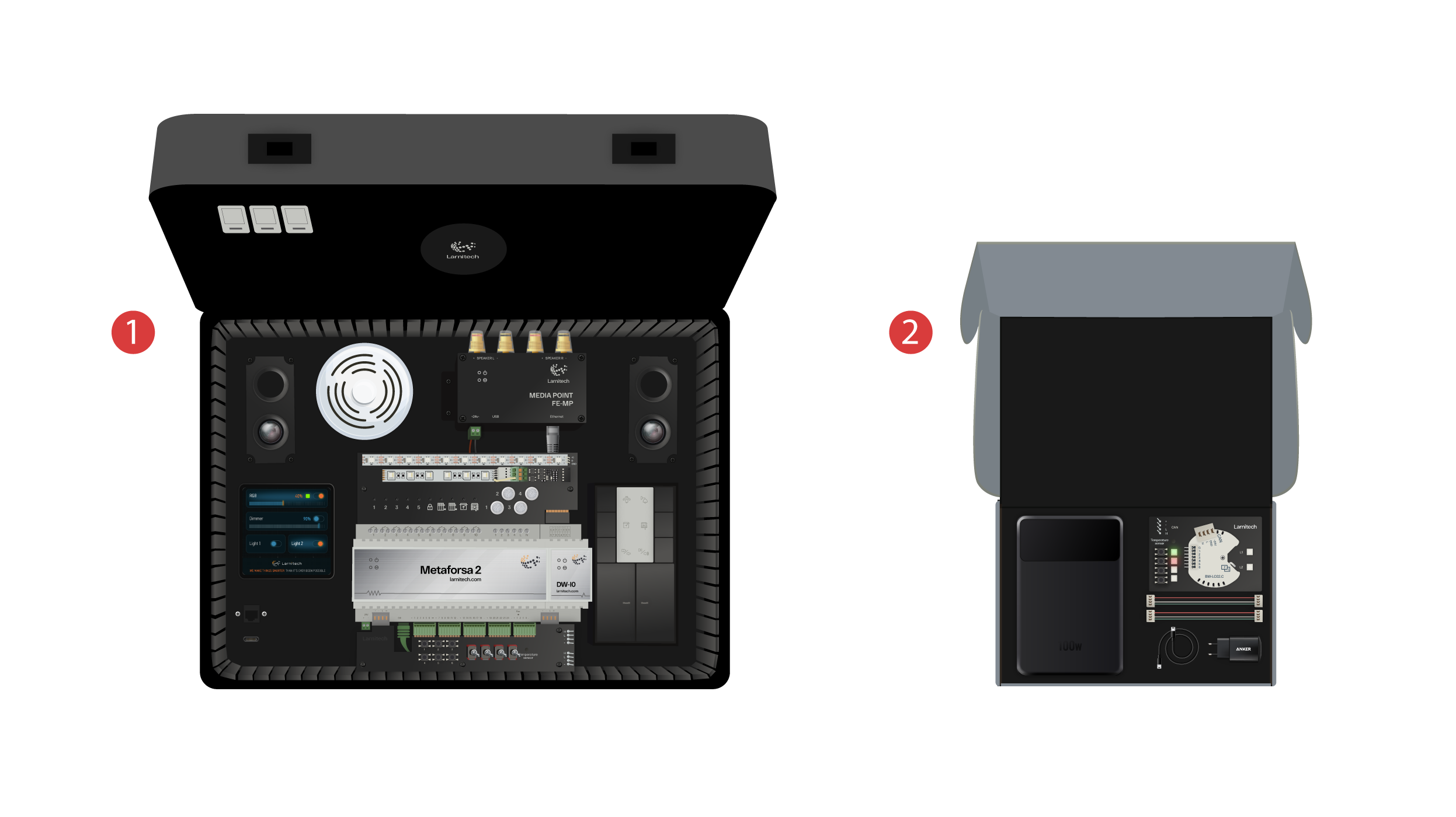
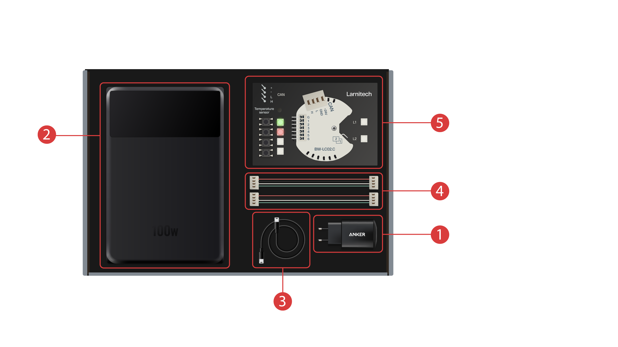
La scatola contiene i seguenti elementi:
① - Un'unità di alimentazione con porta USB di Tipo-C, che supporta la tecnologia Power Delivery;
② - Un power bank con display e porta di output di tipo-C, che può essere utilizzato per alimentare la valigetta dimostrativa;
③ - Cavo di Tipo-C con indicatore di consumo energetico;
④ - 2 cavi CAN bus;
⑤ - Scheda dimostrativa dotata di un modulo BW-LC02 con 2 luci LED, 4 pulsanti con retroilluminazione e un sensore di temperatura collegato ad essa.
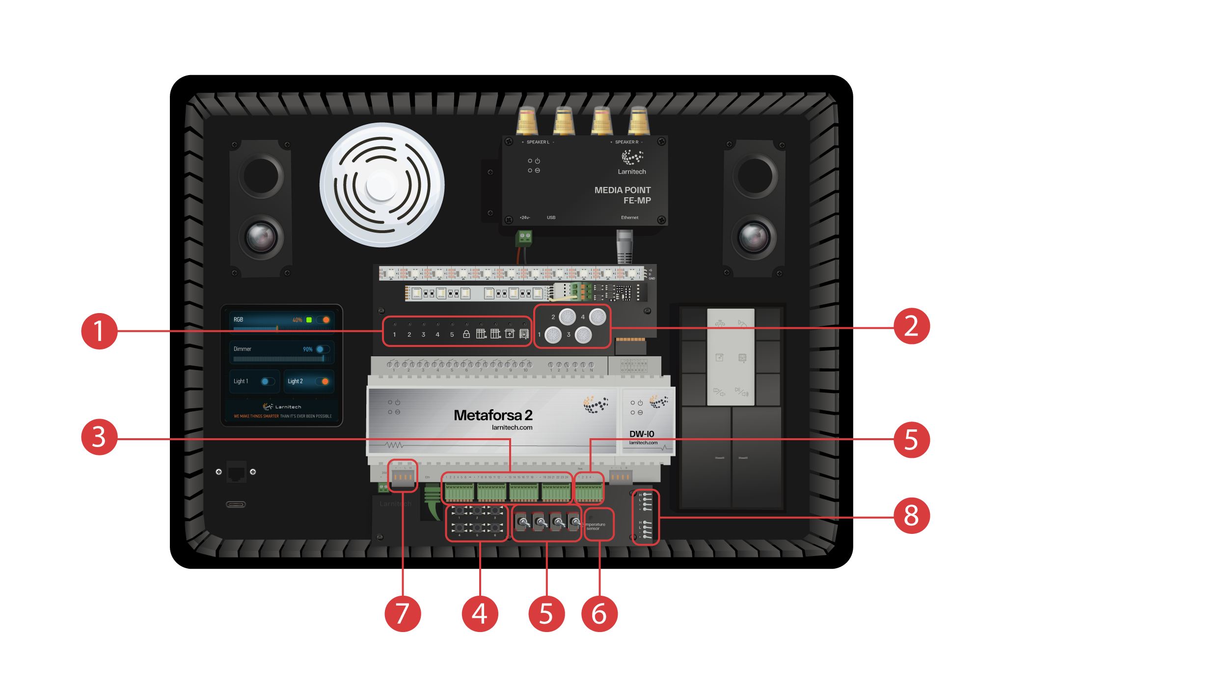
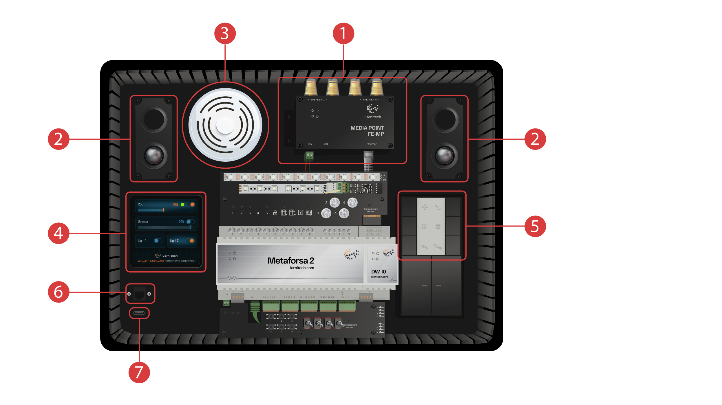
La valigetta dimostrativa contiene i seguenti elementi: Modulo 'Metaforsa 2'.
Il Metaforsa 2" dispone di:
① - Relè a 10 canali con luci LED collegate ad esso, che ne indicano lo stato attuale;
② - 4 canali regolabili, a cui sono collegate delle luci LED regolabili;
③ - 24 canali di input, a cui sono collegati 6 pulsanti ④ e 4 interruttori ⑤ per imitare vari sensori;
⑥ - Canali di input per sensori di temperatura a cui è collegato un sensore;
⑦ - CAN bus per il collegamento di dispositivi aggiuntivi. Ad esso sono collegati altri moduli della valigetta dimostrativa, oltre a 2 porte ⑧ per il collegamento di dispositivi esterni;
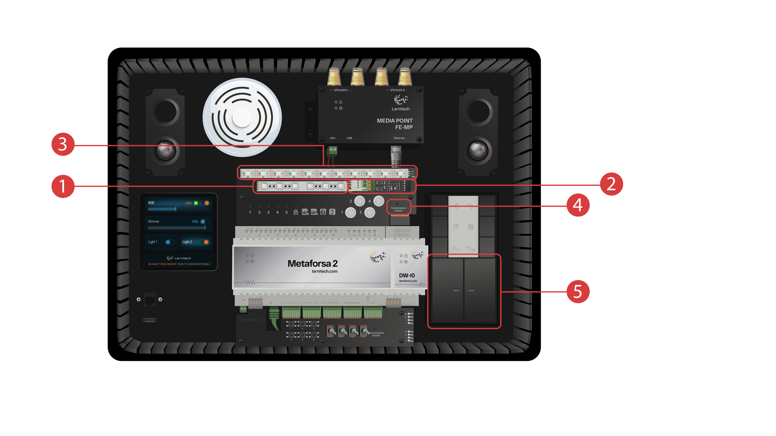
Modulo DW-IO
Questo modulo dispone di 14 canali universali di input/output, ai quali sono collegati i seguenti elementi:
① - Striscia RGBW a 4 canali, collegata tramite l'amplificatore di corrente AMP5V-4 ②;
③ - Una striscia con luci LED indirizzate. Ciascuna di queste luci LED può illuminarsi con un colore specifico;
④ - Sensore di temperatura;
⑤ - E due pulsanti con retroilluminazione.
La valigetta dimostrativa presenta anche:
① - un Media Point FE-MP con ② due altoparlanti;
③ - Un sensore CW-CO2 sei-in-uno, che misura: Livello di movimento, Illuminazione, Temperatura, Umidità, Livello di CO2 ed è dotata di un trasmettitore ad infrarossi;
④ - un pannello sensore da 4 pollici LCP4 che può visualizzare un'interfaccia normale o un'interfaccia adattata ai pannelli a parete;
All'interno della valigetta è presente un modulo di controllo a pulsanti BW-SW24 a cui è collegata una tastiera JUNG a sei pulsanti da 24 volt ⑤.
E un router Wi-Fi, che può essere collegato ad Internet tramite una porta Ethernet ⑥ sul pannello frontale del case o tramite una rete Wi-Fi disponibile.
Per l'alimentazione è presente una porta di tipo C ⑦, situata sul pannello frontale.
Tutte le apparecchiature installate nella valigetta dimostrativa sono alimentate a 20 Volt, in modo assolutamente sicuro per l'utente.
Collegamento del cavo di alimentazione e del cavo Ethernet. Se non si ha la possibilità di connessione via Ethernet, più avanti in questo video mostreremo come collegare il router integrato alla rete Wi-Fi.
Per procedere, è necessario installare l'applicazione Larnitech sul proprio smartphone o tablet. È sufficiente scansionare il primo codice QR presente nella parte superiore della valigetta.
Se dopo l'installazione e l'avvio dell'app la connessione non viene stabilita automaticamente, è necessario collegarsi alla rete Wi-Fi "Larnitech_case_5G" con l'aiuto del proprio dispositivo mobile. Quindi avviare l'app e scansionare il primo codice QR nella sezione "Connessioni".
Potrebbe essere necessario disattivare la connessione dati sul dispositivo mobile se il kit dimostrativo non è connesso ad Internet.

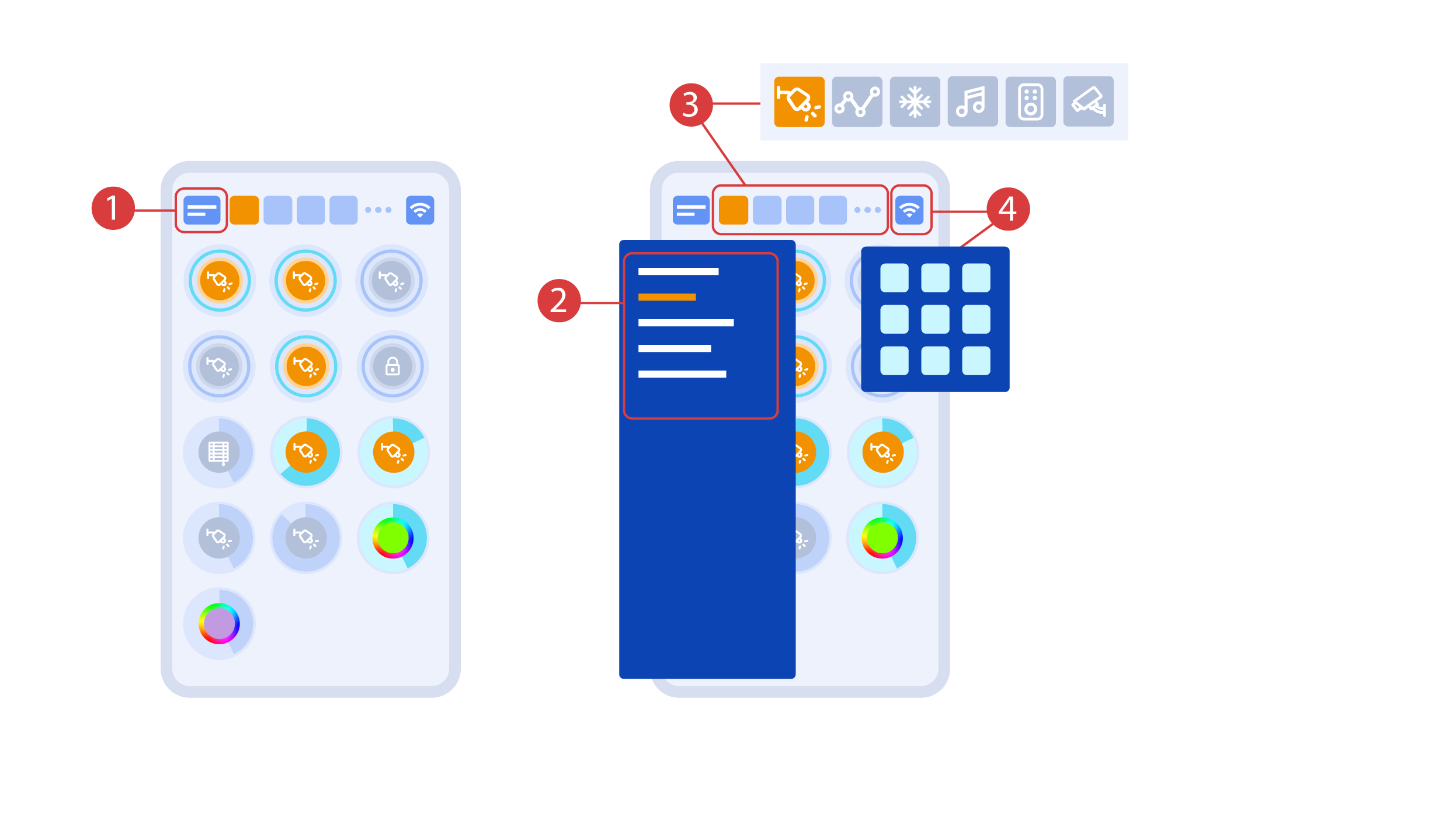
La schermata principale dell'app presenta diversi elementi chiave. Nell'angolo in alto a sinistra si trova il menu "Seleziona area" ①.
Basta fare clic su una delle aree disponibili per avviare la gestione di essa ②.
Ci sono anche delle icone che permettono di selezionare gli esecutori, i sensori, il meteo, i file multimedia, i telecomandi e le telecamere ③. Sull'angolo destro è presente un'icona per il menu aggiuntivo ④. All'interno dell'icona è possibile visualizzare anche lo stato della connessione attuale.
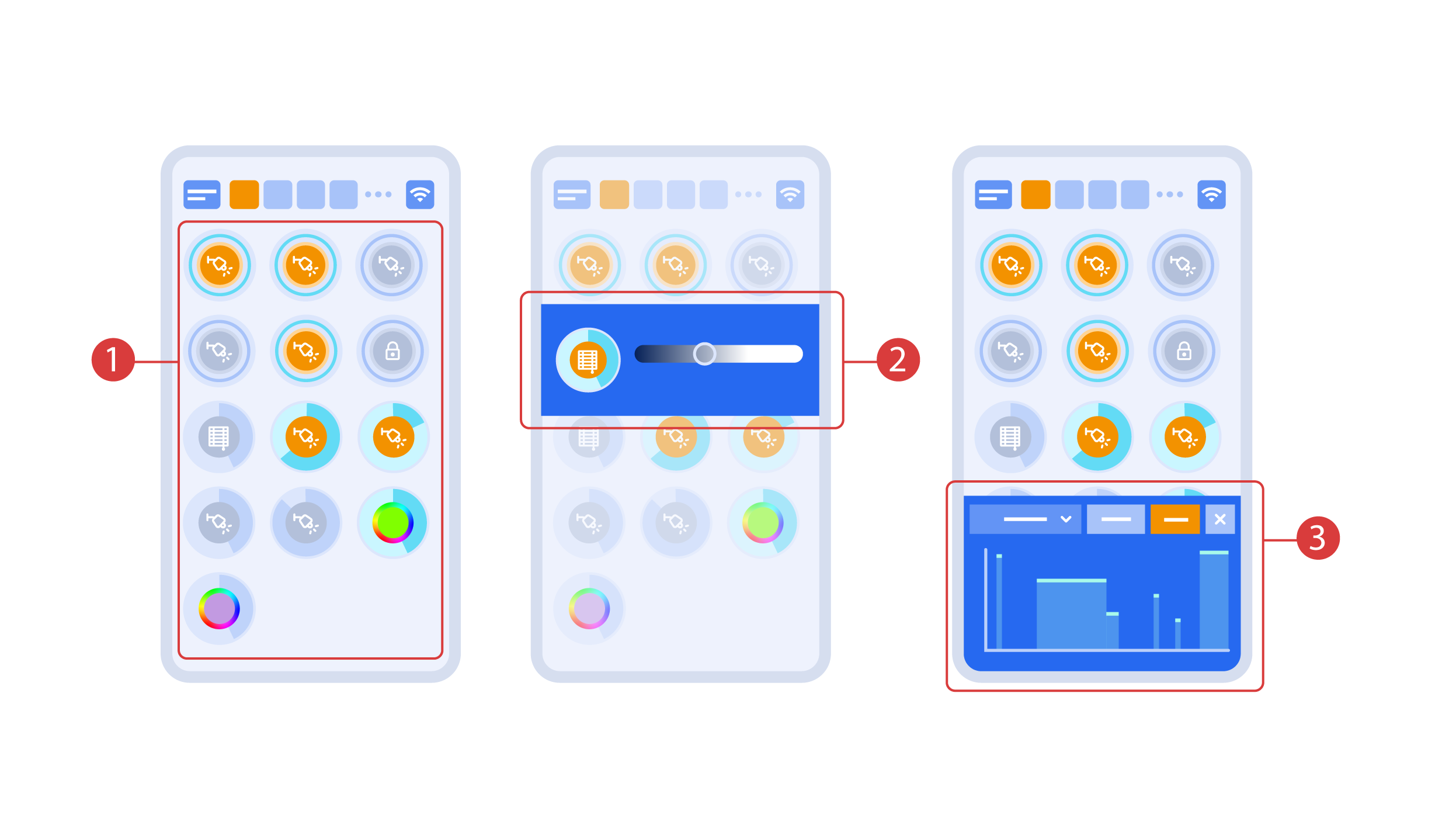
Turning the executors ① on or off is done with a simple click. In order to change the level of lighting ②, color of lights or the position of the blinds, use a double click. In order to access the status history ③ of this executor or sensor, press and hold the icon for one second.
A short press of the physical buttons on the panel turns the light on or off. Press and hold the button to change the light brightness.
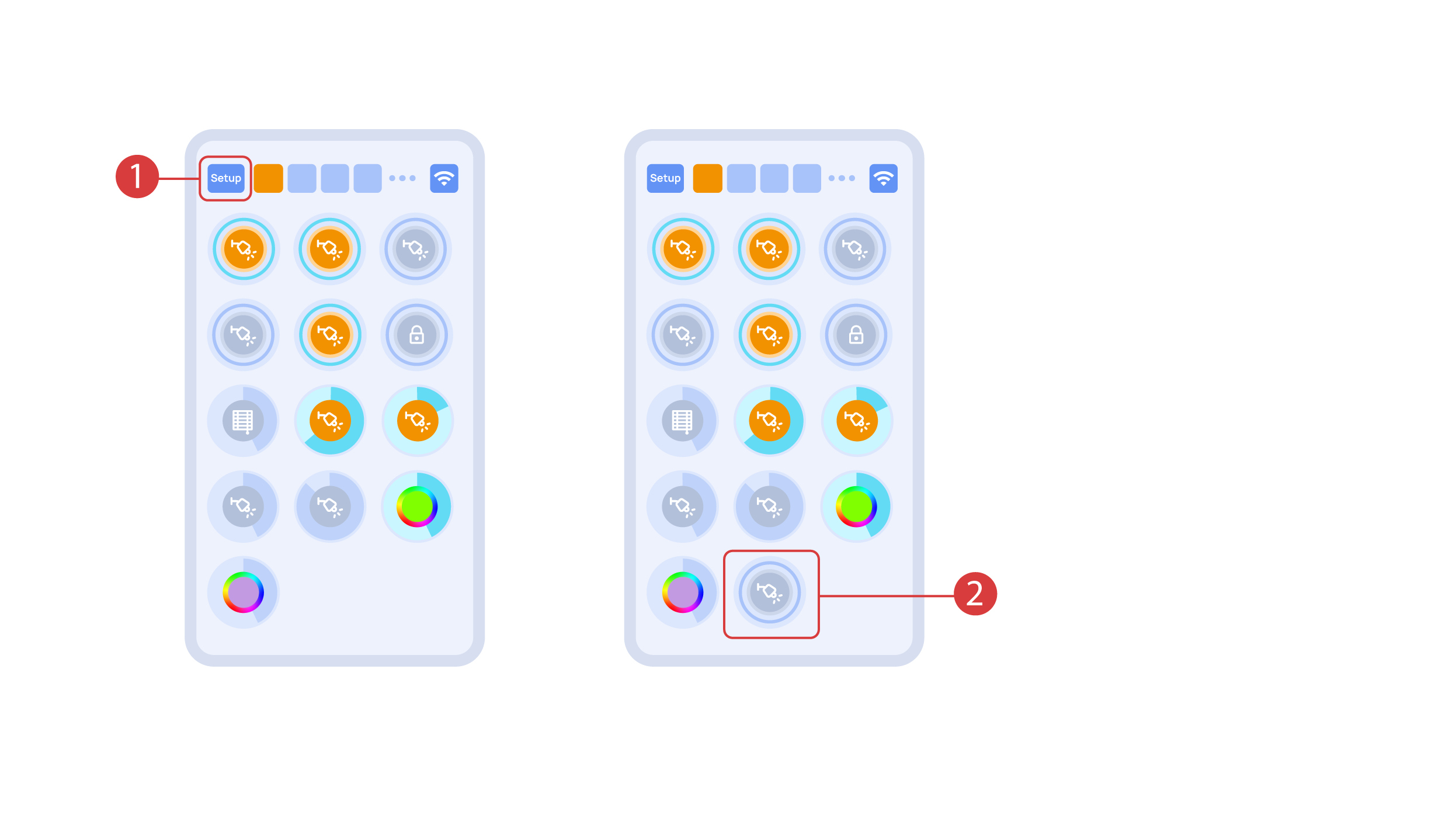
In order to demonstrate the Plug and Play function, we open the executors in the Setup area ① and connect the module to the CAN bus. The system automatically detects the new module and adds it to the ‘Setup’ area, ② where we are able to control the new module instantly.
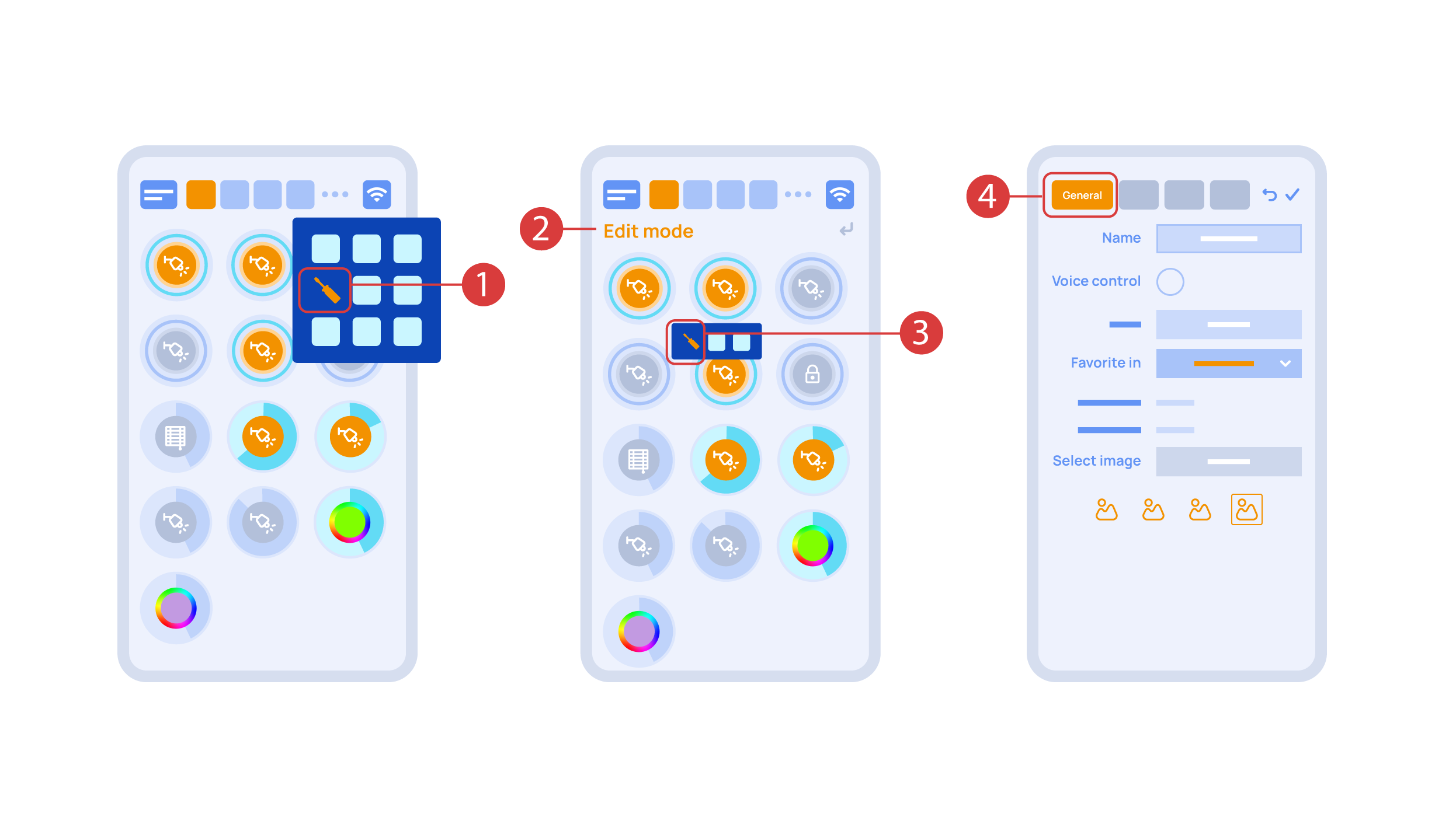
Now we can set up these executors. In order to do this, enter the additional menu ① and activate the edit mode, by pressing the appropriate icon .
Now we are in the edit mode ②, which can be seen from the appropriate notification in the top part of the screen. In this mode, when we press and hold an icon, we can move it among other elements and place it into another Room by placing it in the Area-choosing Menu and then choosing the area that we need. A long press ③ of the element starts the menu, from which we set up the current element.In the ‘General’ ④ section we can change the name of the element, add a voice command for it, change an icon or add the element to ‘Favorites’.
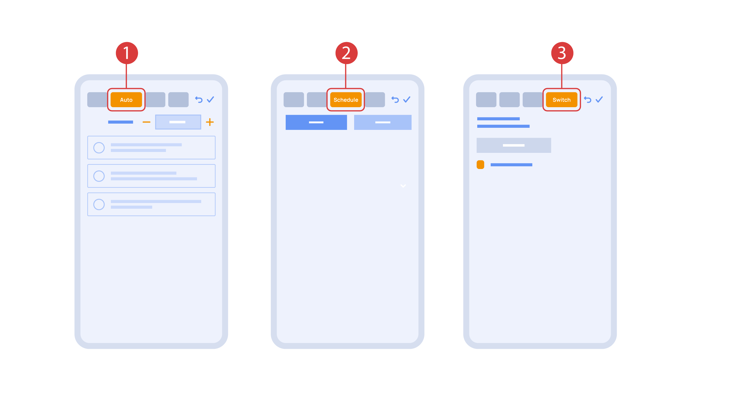
‘Auto’ section ① lets us activate the automation with a few clicks, as well as set up its parameters.
In the ‘schedule’ section ②, you can determine the schedule when the given element will turn on or off, including by using the time of the setting and rising of the sun.
The ‘Switches’ tab ③ lets you bind a button to control the executor.
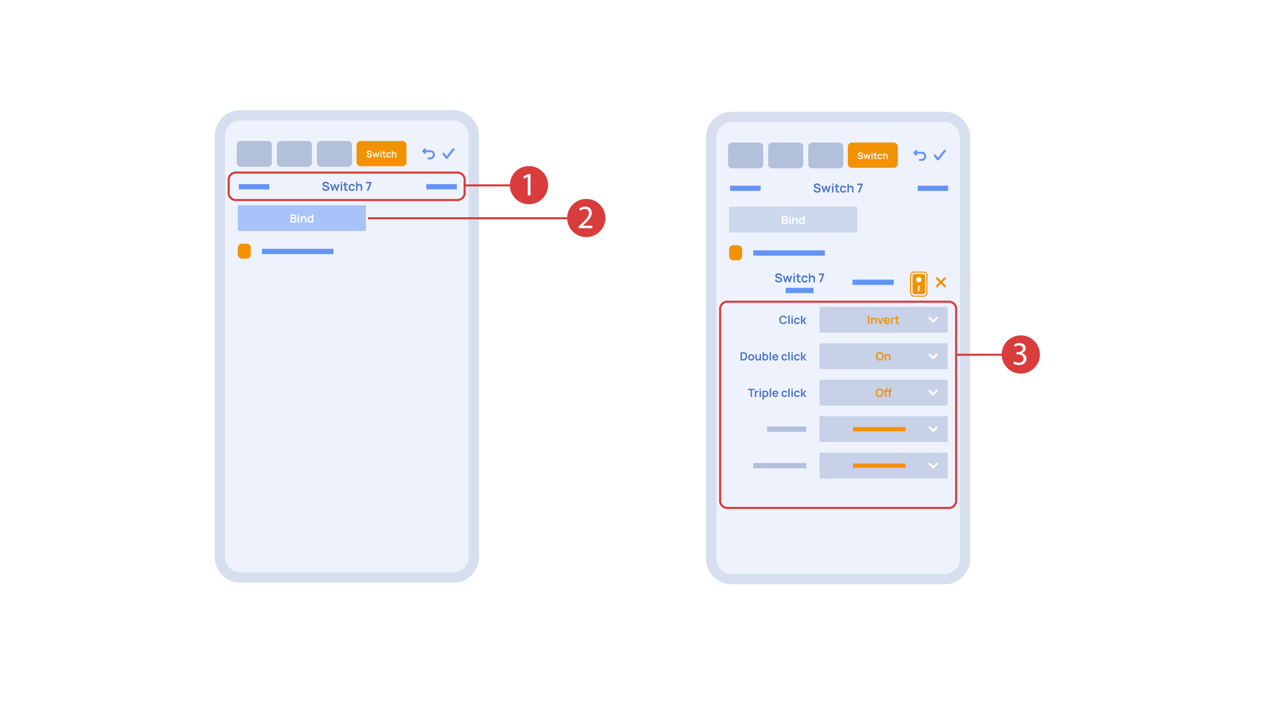
In order to do this, ① we press the button we need to bind. The system displays it, after which we press ‘Bind’② and save the changes. Now this button controls the executor
The ‘Switches’ tab ③ also features additional button setup options. For example, we can program the executor to be controlled with a double or triple click of a button, as well as define an action performed by this, for example ‘only turning on’ or ‘only turning off’ an executor. In this case we are setting up the button to do the following: one click will cause the lamp to toggle, a double click will turn it on and a triple click will turn it off. In this way a single button can perform up to five different actions.
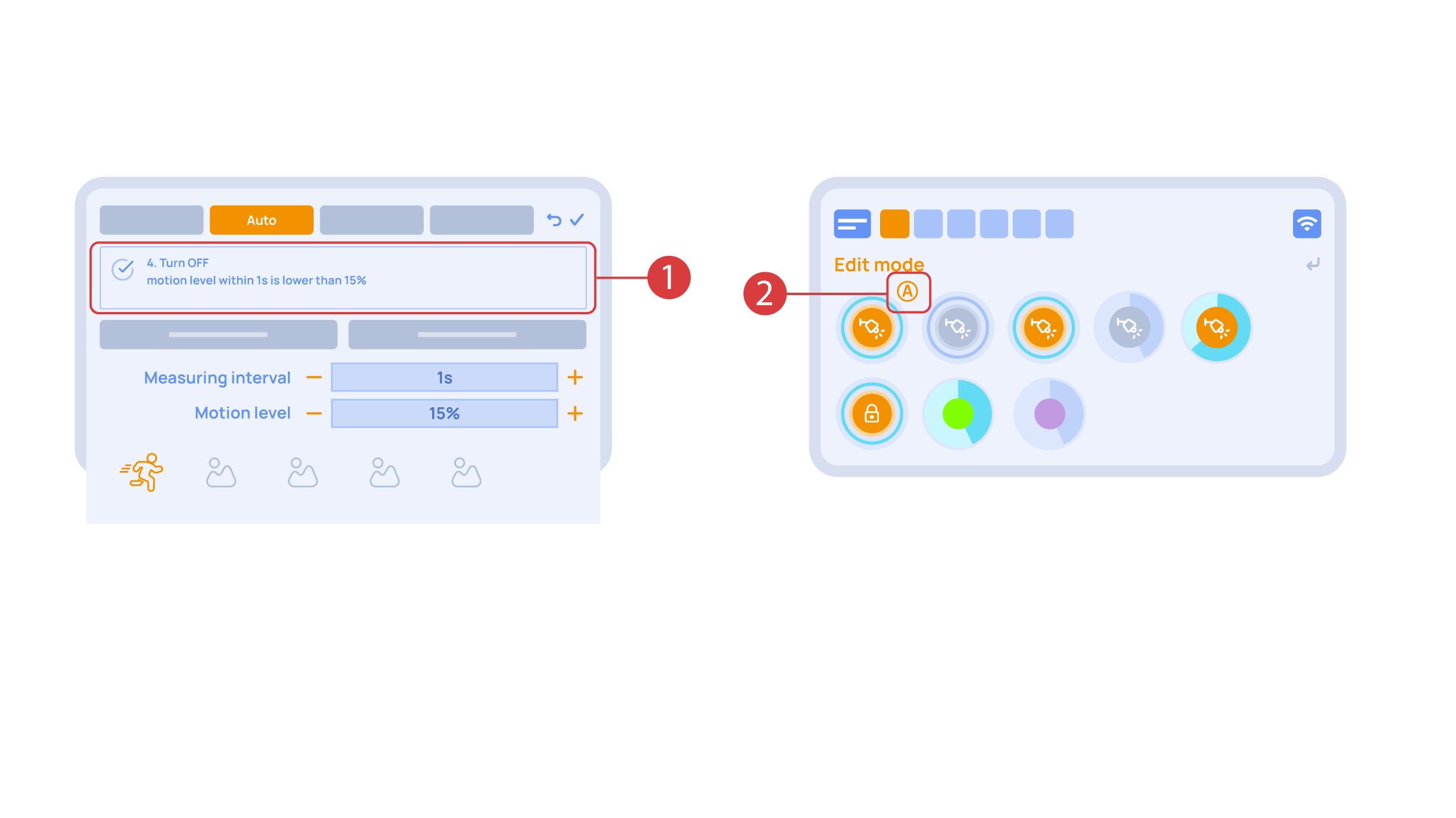
Let’s also set up basic automation of turning an executor on or off with the help of a motion sensor.
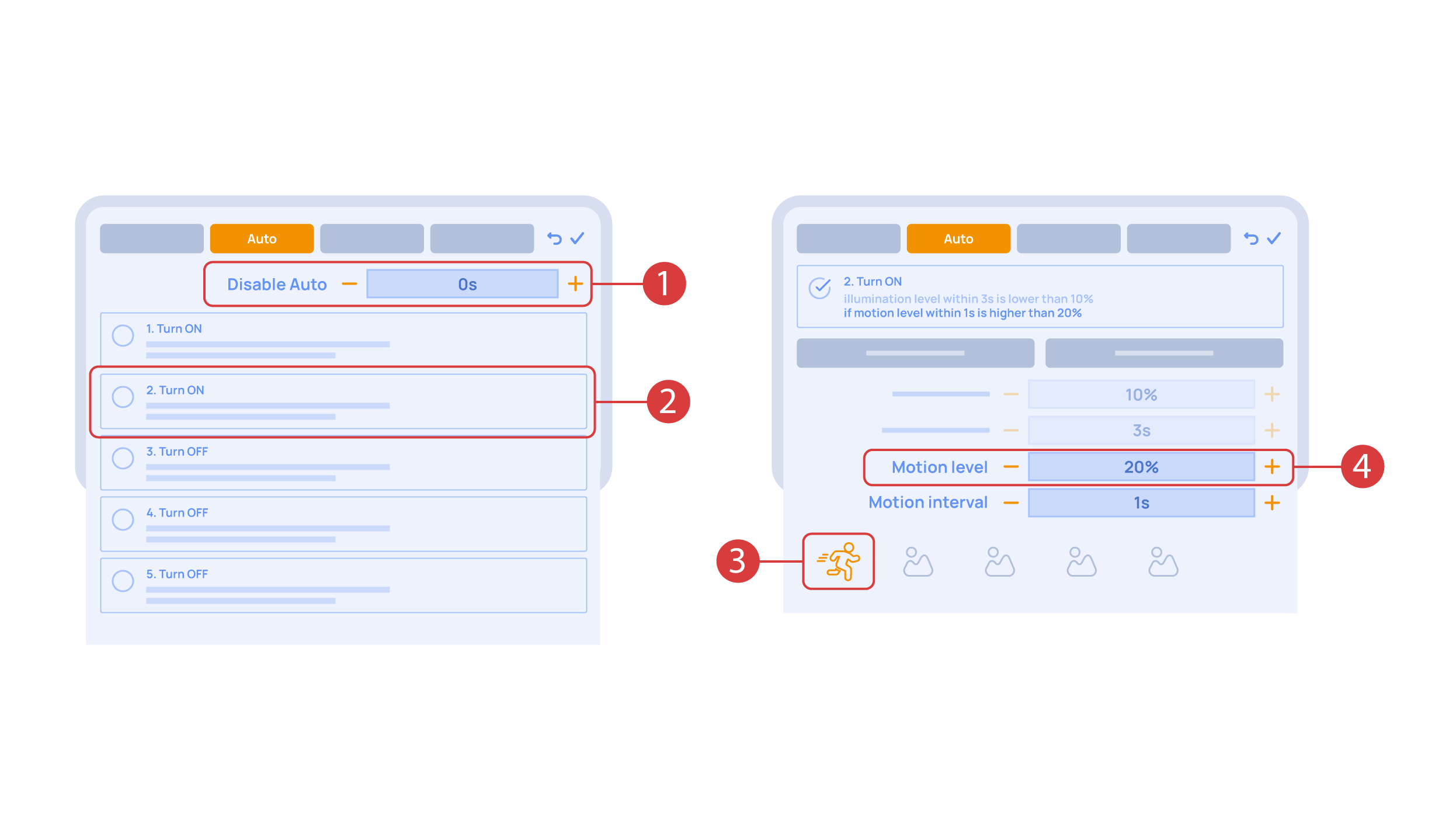
The ‘Auto period’ ① option sets the time for which the automation is disabled after an executor is manually controlled.For our demonstration purposes, we will set it to zero.
Then we will activate the automation ② to turn on the executor when motion is detected. We choose the motion sensor ③ and the level of motion ④. We can also choose a light sensor and its parameters.
Now we will activate turning off ① of an executor if there is no motion: we choose the same sensor, set a lower threshold and a minimal time.Save the changes.
The extra ‘A’ icon ② will be added to the executor icon, meaning that automation has been set up for it. Now the lamp will be turned on when motion is detected and instantly turned off when no motion is detected.
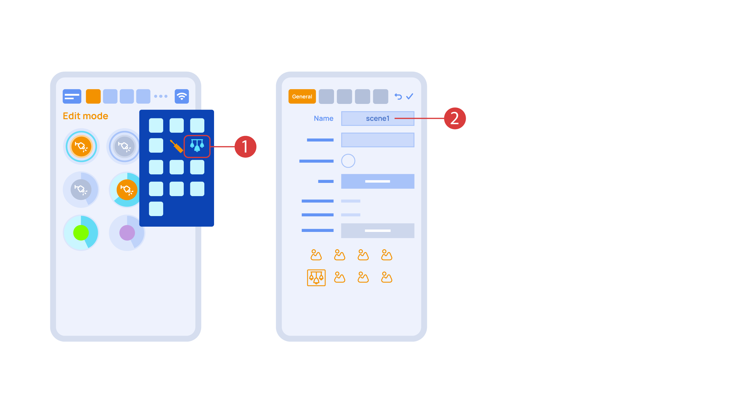
Let’s create a light scheme. For this we need to select the appropriate item in the additional menu ①. Give the light scheme a name ②.
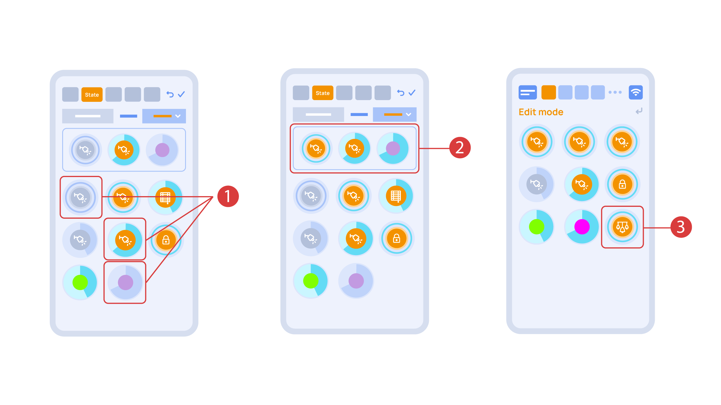
In the ‘State’ tab, use a long press to add the lights we want to use into the light scene ① and set up their state ②. ‘Auto’, ‘Schedule’, ‘Switch’ tabs are the same for all the executors.
Save the changes and we are able to use the newly-created light scheme ③ immediately.
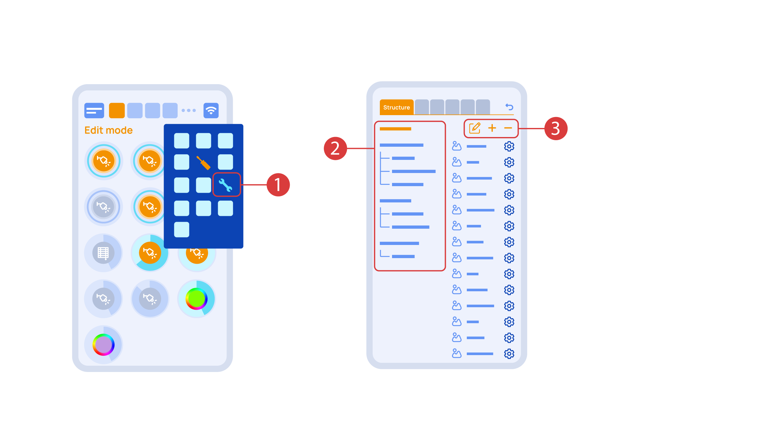
While you are in the Edit Mode, there is a ‘Setup’ ① icon in the additional menu.
Here in the ‘Structure’② tab we can see all the areas.
We can create new ones ④, rename them and move the elements around.
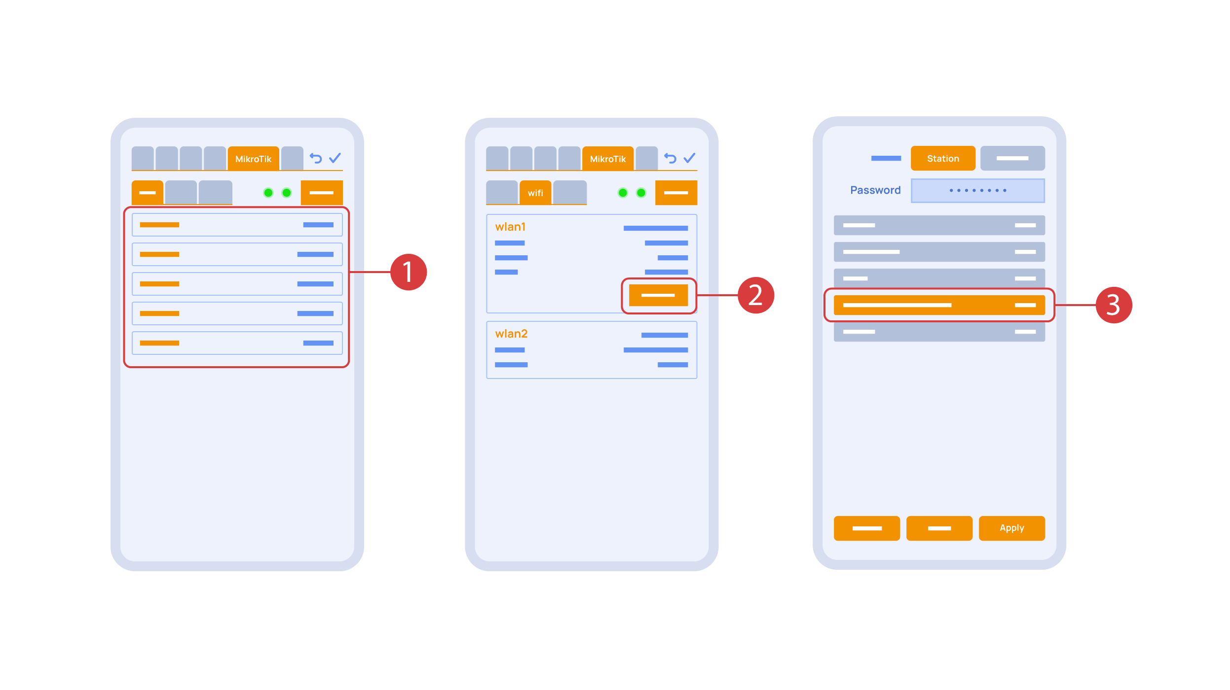
In the ‘Mikrotik’ tab ① you can see the current parameters of your router, which you can also connect to your local Wi-Fi network.
In order to do this, enter the Wi-Fi sub-menu, click the wlan1 interface configuration ②, after which choose the ‘station’ mode, choose a Wi-Fi network out of the list ③ of available ones and enter the connection password.
In the ‘Backups’ tab ① you can see the list of saved configurations, which can be restored if necessary.

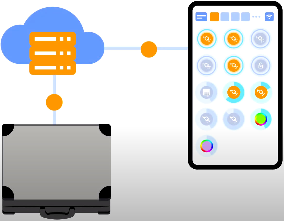
For cloud access to the device, you do not need any extra settings. The app detects the absence of the system in your local network and automatically establishes the connection via the cloud.
We thank you for watching this tutorial! If you have questions or need extra help, please do not hesitate to refer to our technical support team. See you in the next episodes!