Difference between revisions of "Quick Start Guide/nl"
(Created page with "Het aan- of uitzetten van de executeurs <span style="font-size: 30px; vertical-align: middle;">①</span> is met een simpele klik gedaan Om het verlichtingsniveau <span st...") |
(Created page with "Om de Plug and Play-functie te demonstreren, openen we de executeurs in het Setup-gebied <span style="font-size: 30px; vertical-align: middle;">①</span> en sluit de modu...") |
||
| Line 86: | Line 86: | ||
<hr> | <hr> | ||
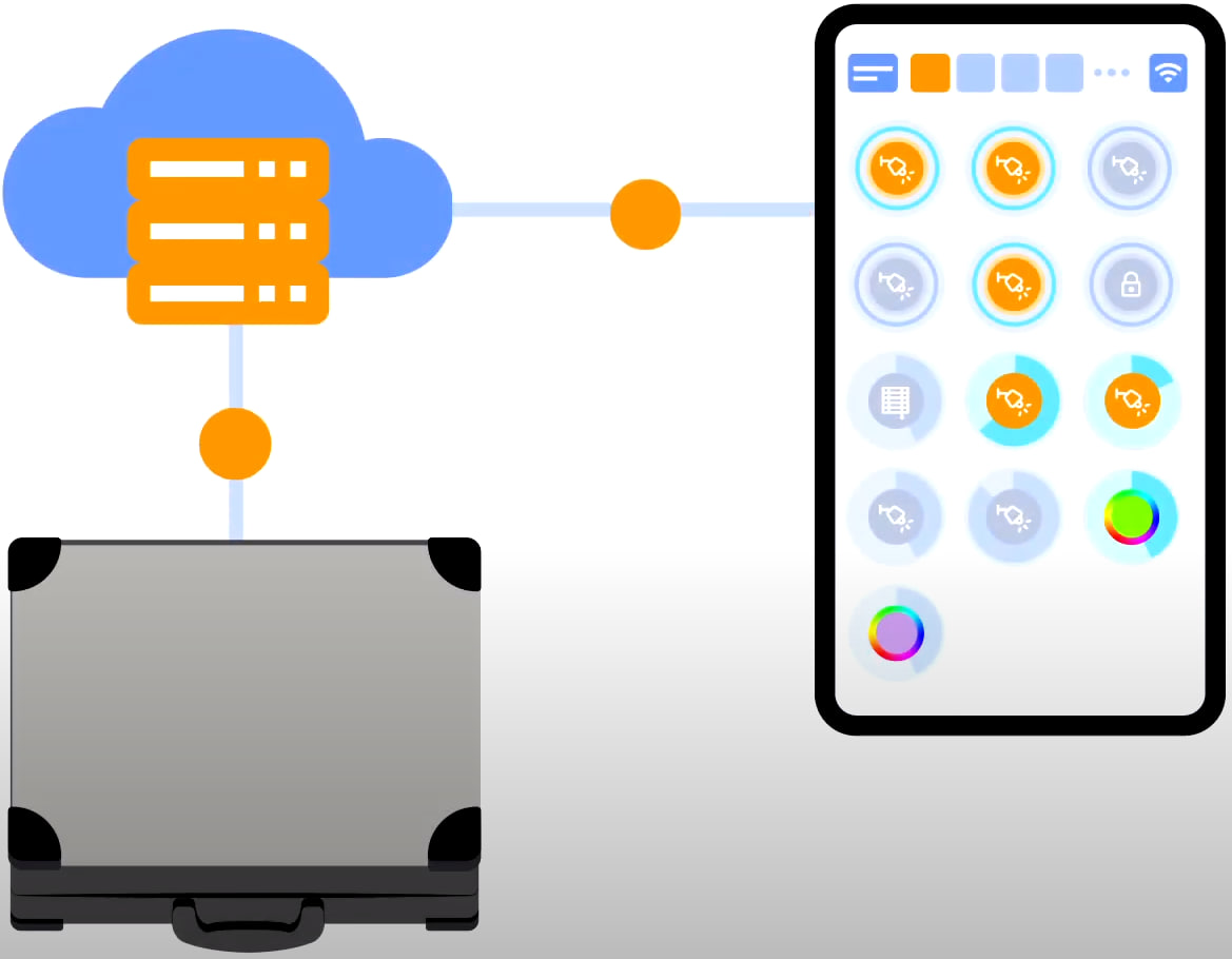
| − | + | Om de Plug and Play-functie te demonstreren, openen we de executeurs in het Setup-gebied <span style="font-size: 30px; vertical-align: middle;">①</span> en sluit de module aan op de CAN-bus. Het systeem detecteert automatisch de nieuwe module en voegt deze toe aan het gebied ‘Setup’, <span style="font-size: 30px; vertical-align: middle;">②</span> waar we de nieuwe module direct kunnen bedienen. | |
[[File:DemoCase9.png|1000x800px]] | [[File:DemoCase9.png|1000x800px]] | ||
<hr> | <hr> | ||
Revision as of 09:04, 9 November 2023
Snelle start/uitpakken.
Wij heten iedereen welkom op ons kanaal! Deze video is een handleiding voor het snel en moeiteloos opzetten van het Larnitech-systeem. De opstelling zal gebeuren met behulp van een demonstratiekoffer. Een trainingsset bestaat uit een demonstratiekoffer ① en een doos met diverse extra items ②.
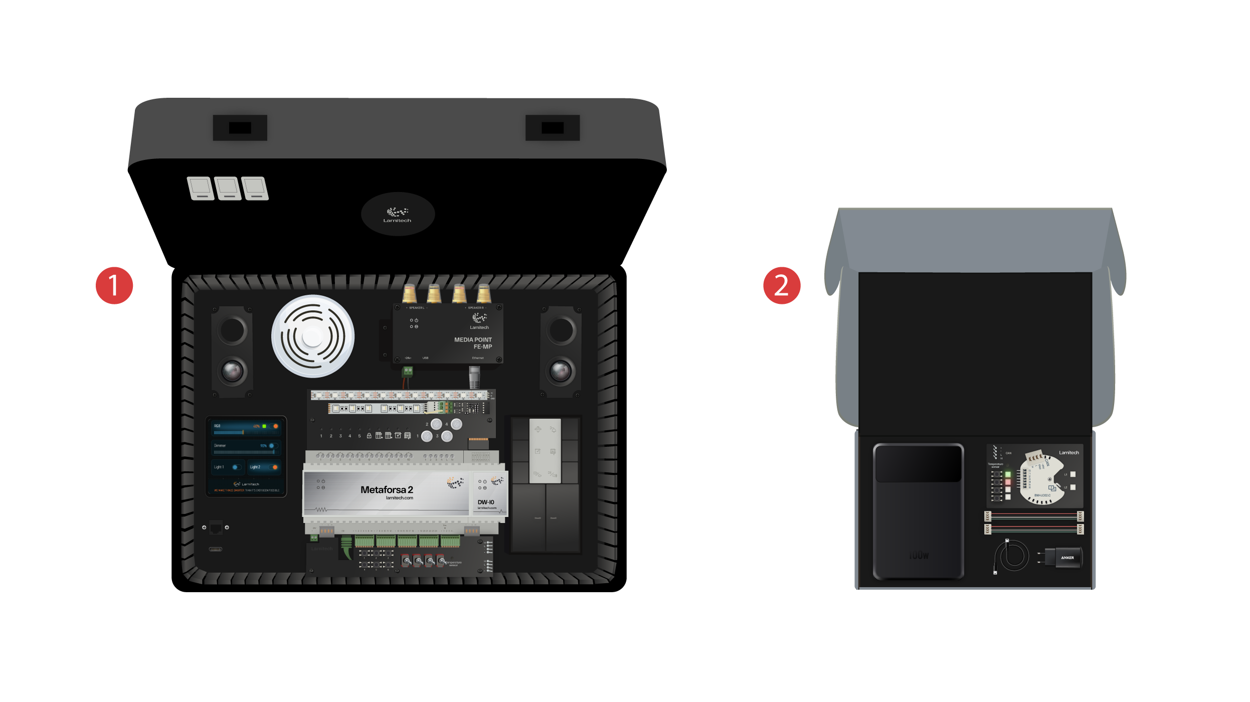
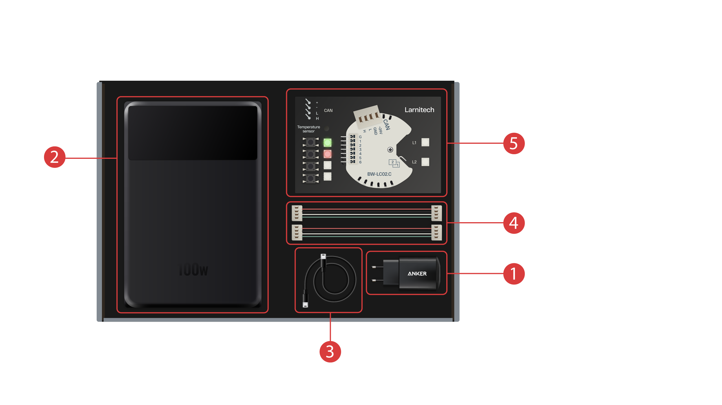
De doos bevat het volgende:
① - Een voedingseenheid met Type-C USB-poort, die de Power Delivery-technologie ondersteunt;
② - Een powerbank met display en Type-C-uitgang, die kan worden gebruikt om de demonstratiekoffer van stroom te voorzien;
③ - Type-C-kabel met een energieverbruiksindicator;
④ - 2 CAN-buskabels;
⑤ - Demonstratiebord met een BW-LC02-module met 2 LED-lampjes, 4 knoppen met achtergrondverlichting en een daarop aangesloten temperatuursensor.
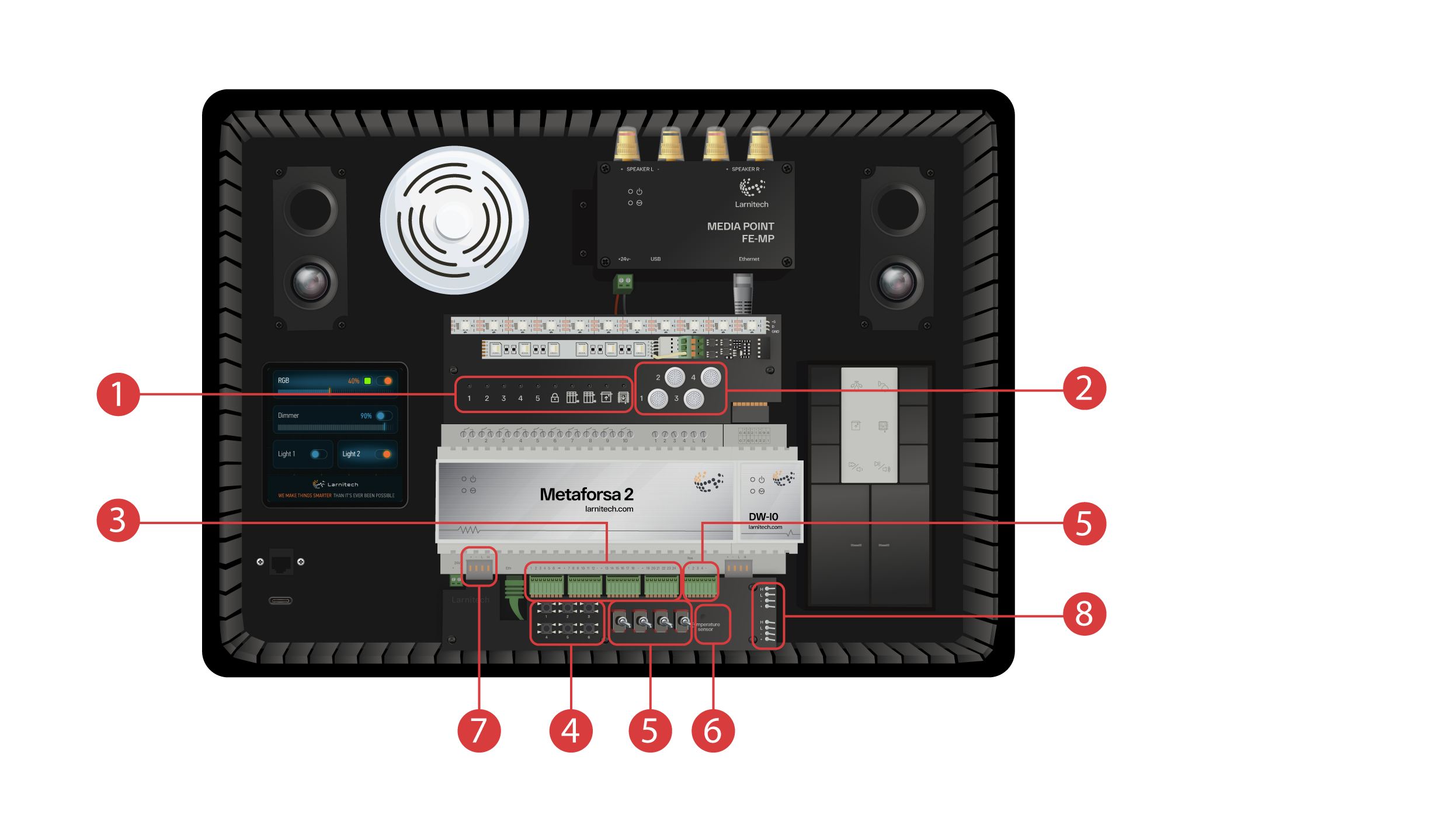
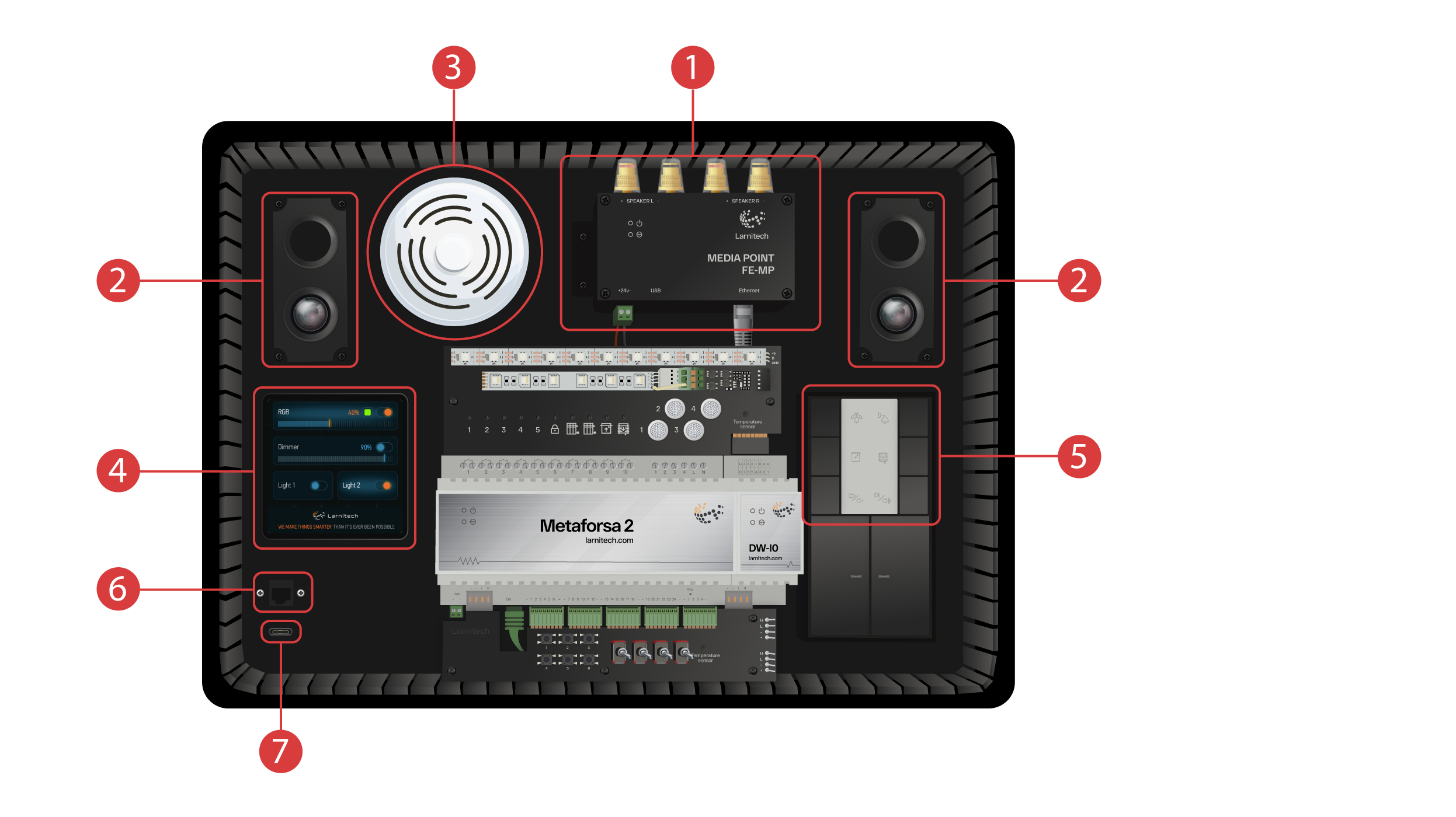
De demonstratiekoffer bevat de volgende elementen: Module ‘Metaforsa 2’.
‘Metaforsa 2’ heeft:
① - 10 relaiskanalen met daarop aangesloten LED-lampjes, die hun huidige status aangeven;
② - 4 dimbare kanalen, met daarop aangesloten dimbare LED-lampen;
③ - 24 ingangskanalen, met daarop 6 knoppen ④ en 4 schakelaars ⑤ caangesloten om verschillende sensoren te imiteren;
⑥ - Input channels for temperature sensors with one sensor connected to it;
⑦ - CAN-bus voor het aansluiten van extra apparaten. Er zijn andere modules van de demonstratiekoffer op aangesloten, evenals 2 poorten ⑧ voor het aansluiten van externe apparaten.
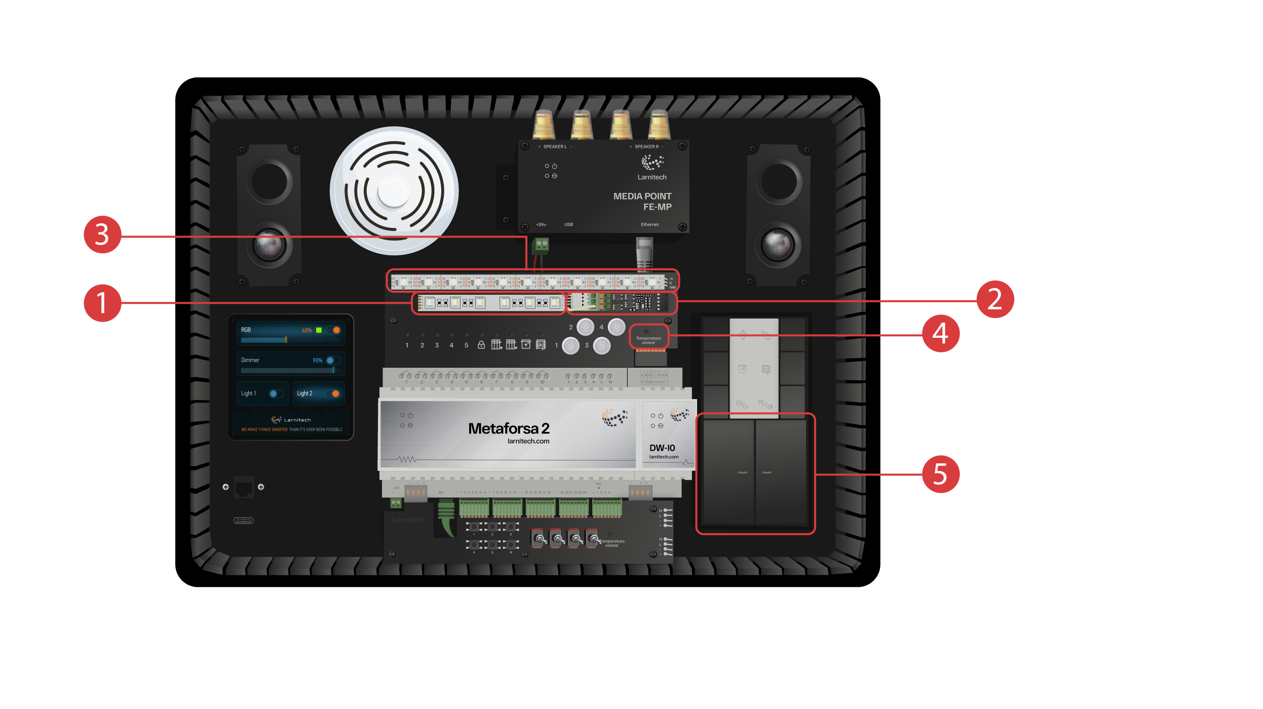
DW-IO module
Deze module heeft 14 universele in-/uitgangskanalen, waarop de volgende items zijn aangesloten:
① - 4-kanaals RGBW-strip, aangesloten via de AMP5V-4 ② stroomversterker;
③ - Een strip met geadresseerde LED-verlichting. Elk van deze LED-lampen kan schijnen met zijn eigen individuele kleur;
④ - Temperatuursensor;
⑤ - En twee knoppen met achtergrondverlichting.
De demonstratiekoffer beschikt ook over het volgende:
① - een Media Point FE-MP met ② twee luidsprekers;
③ - Een zes-in-één CW-CO2-sensor, die meet: Bewegingsniveau, verlichting, temperatuur, vochtigheid, CO2-niveau en met een infraroodzender;
④ - een 4-inch sensorpaneel LCP4 dat een gewone interface of een interface aangepast voor wandpanelen kan weergeven;
In de behuizing bevindt zich een knopbedieningsmodule BW-SW24, waarop een 24 volt JUNG-toetsenbord met zes knoppen ⑤ is aangesloten;
En een Wi-Fi-router, die verbinding kan maken met internet via een ethernetpoort ⑥ op het voorpaneel van de behuizing of via een beschikbaar Wi-Fi-netwerk;
Voor de stroomvoorziening is er een Type-C-poort ⑦, die zich op het voorpaneel bevindt.
Alle apparatuur die in de demonstratiekoffer is geïnstalleerd, wordt gevoed met 20 Volt, wat absoluut veilig is voor de gebruiker.
Sluit de voedingskabel en de Ethernet-kabel aan. Als u niet over de mogelijkheid beschikt om via Ethernet verbinding te maken, demonstreren we verderop in deze video hoe u de ingebouwde router op uw Wi-Fi-netwerk kunt aansluiten.
Om verder te kunnen gaan, moet de Larnitech-app op uw smartphone of tablet worden geïnstalleerd. Scan gewoon de eerste QR-code vanaf de bovenkant van uw koffer.
Als na het installeren en starten van de applicatie de verbinding niet automatisch tot stand wordt gebracht, moet u met behulp van uw mobiele apparaat verbinding maken met het Wi-Fi-netwerk ‘Larnitech_case_5G’. Start vervolgens de applicatie en scan de eerste QR-code in het gedeelte ‘Verbindingen’.
Mogelijk moet u de gegevensoverdracht op uw mobiele apparaat uitschakelen als de demonstratieset niet met internet is verbonden.

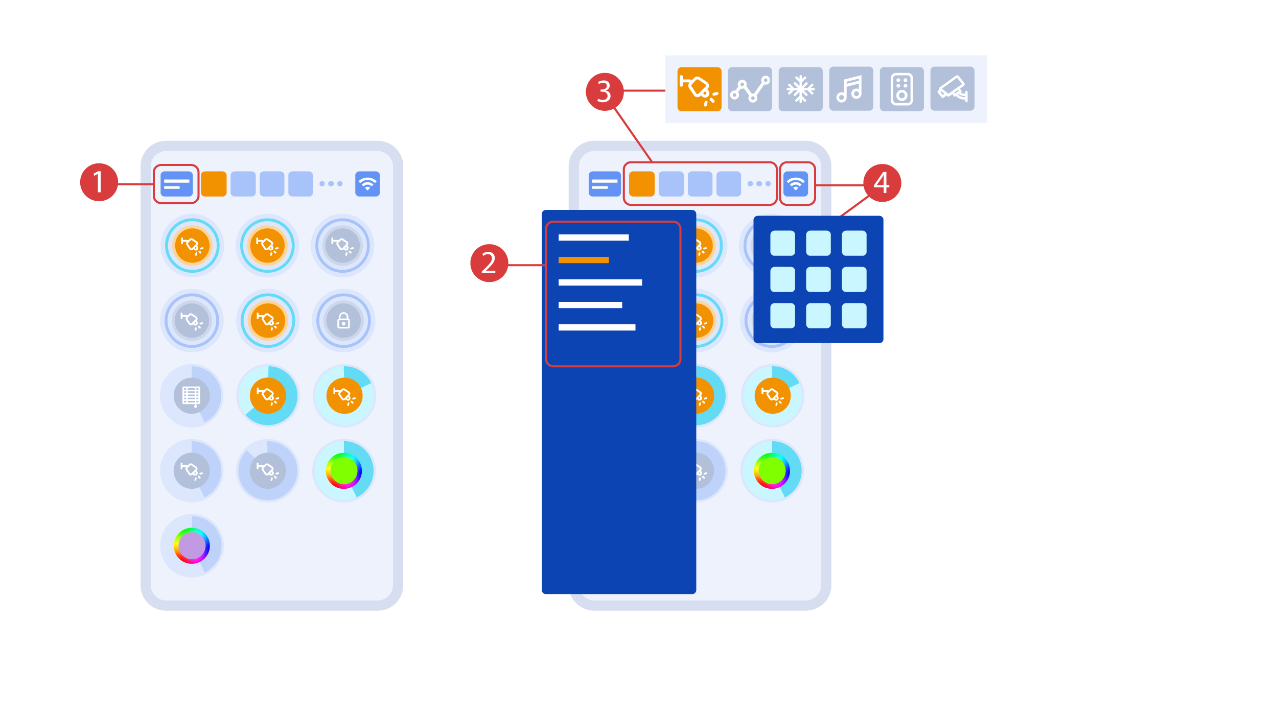
Het hoofdscherm van de app heeft verschillende belangrijke elementen. In de linkerbovenhoek bevindt zich het menu ‘gebied selecteren’ ①.
Klik gewoon op een van de beschikbare gebieden om deze te beheren ②.
Dan zijn er iconen waarmee je de uitvoerders, sensoren, klimaat, multimedia, afstandsbedieningen en camera's kunt kiezen ③. In de rechterhoek staat een pictogram voor het extra menu ④. Binnen het pictogram kunt u ook de status van de huidige verbinding zien.
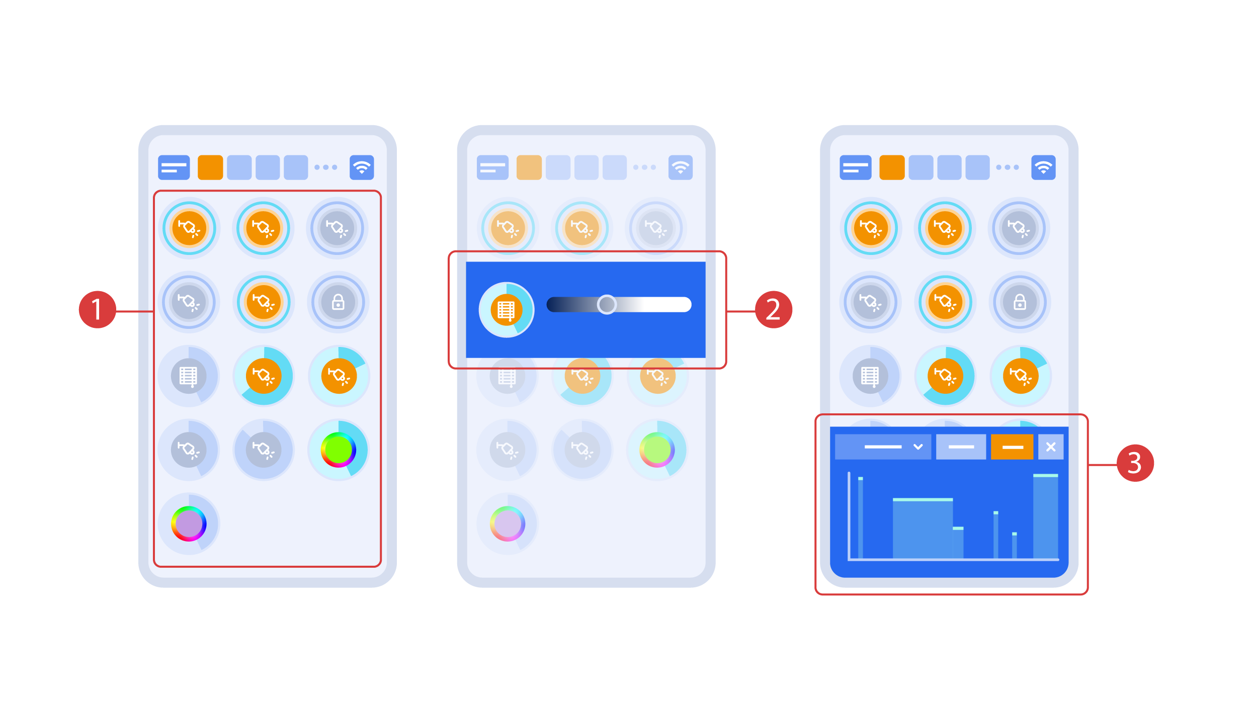
Het aan- of uitzetten van de executeurs ① is met een simpele klik gedaan Om het verlichtingsniveau ②, de kleur van de verlichting of de positie van de jaloezieën te wijzigen, gebruikt u een dubbelklik. Om toegang te krijgen tot de statusgeschiedenis ③ van deze uitvoerder of sensor, houdt u het pictogram één seconde ingedrukt.
Een korte druk op de fysieke knoppen op het paneel schakelt het licht aan of uit. Houd de knop ingedrukt om de helderheid van het licht te wijzigen.
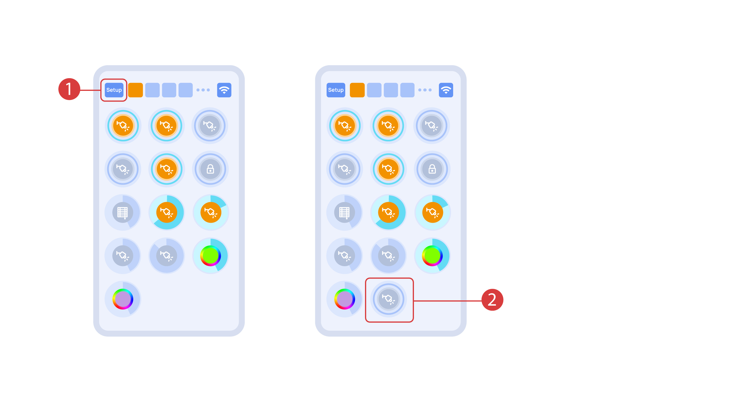
Om de Plug and Play-functie te demonstreren, openen we de executeurs in het Setup-gebied ① en sluit de module aan op de CAN-bus. Het systeem detecteert automatisch de nieuwe module en voegt deze toe aan het gebied ‘Setup’, ② waar we de nieuwe module direct kunnen bedienen.
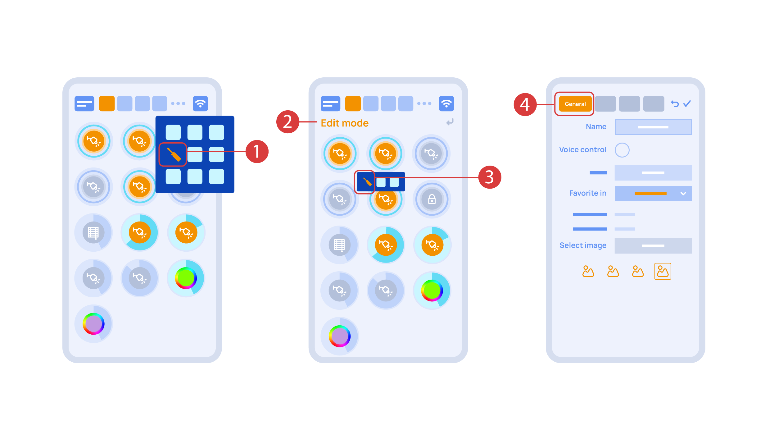
Now we can set up these executors. In order to do this, enter the additional menu ① and activate the edit mode, by pressing the appropriate icon.
Now we are in the edit mode ②, which can be seen from the appropriate notification in the top part of the screen. In this mode, when we press and hold an icon, we can move it among other elements and place it into another Room by placing it in the Area-choosing Menu and then choosing the area that we need. A long press ③ of the element starts the menu, from which we set up the current element.In the ‘General’ ④ section we can change the name of the element, add a voice command for it, change an icon or add the element to ‘Favorites’.
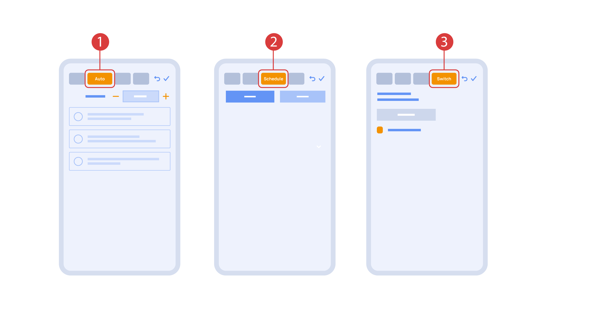
‘Auto’ section ① lets us activate the automation with a few clicks, as well as set up its parameters.
In the ‘schedule’ section ②, you can determine the schedule when the given element will turn on or off, including by using the time of the setting and rising of the sun.
The ‘Switches’ tab ③ lets you bind a button to control the executor.
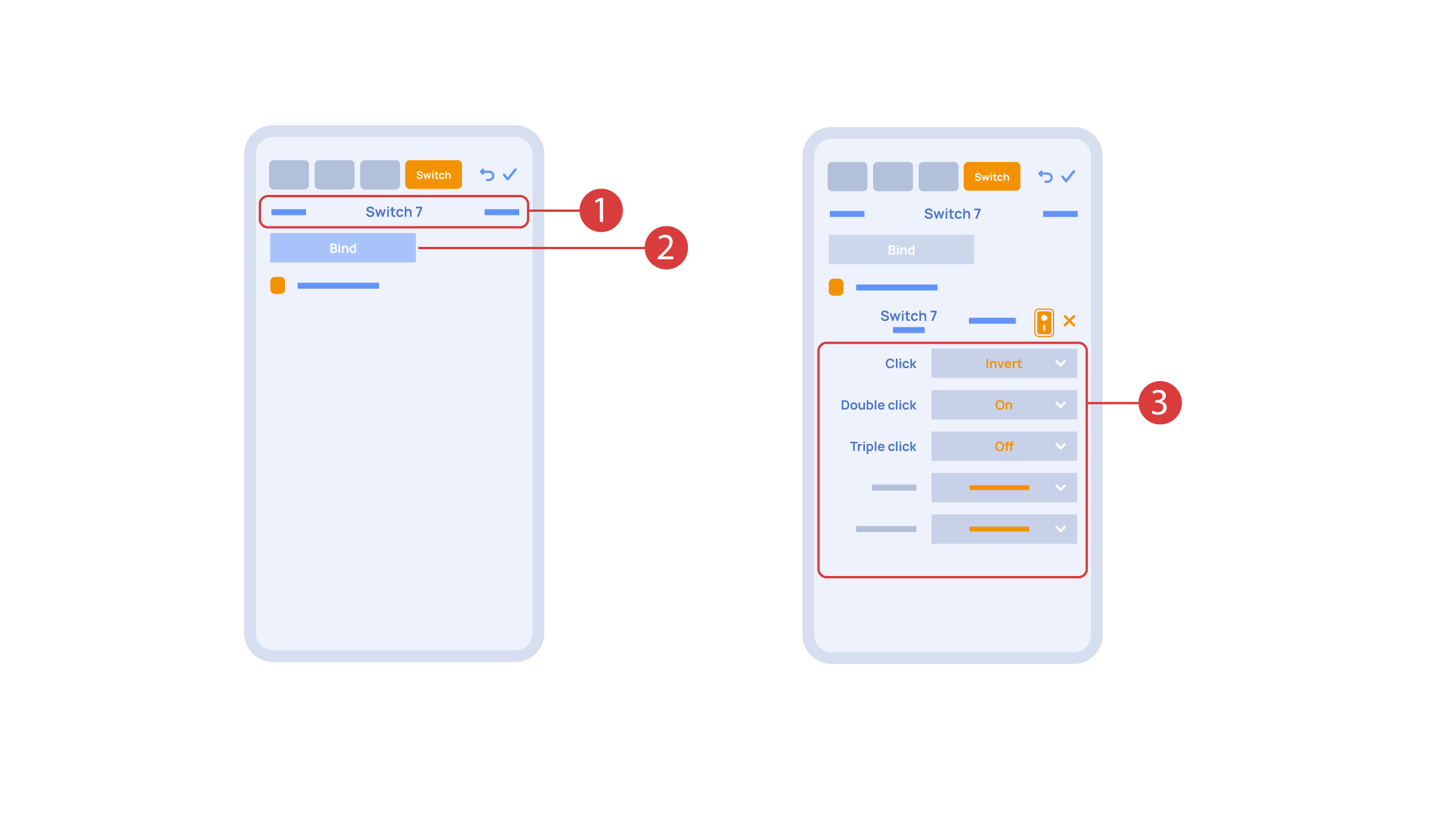
In order to do this, ① we press the button we need to bind. The system displays it, after which we press ‘Bind’② and save the changes. Now this button controls the executor
The ‘Switches’ tab ③ also features additional button setup options. For example, we can program the executor to be controlled with a double or triple click of a button, as well as define an action performed by this, for example ‘only turning on’ or ‘only turning off’ an executor. In this case we are setting up the button to do the following: one click will cause the lamp to toggle, a double click will turn it on and a triple click will turn it off. In this way a single button can perform up to five different actions.
Let’s also set up basic automation of turning an executor on or off with the help of a motion sensor.
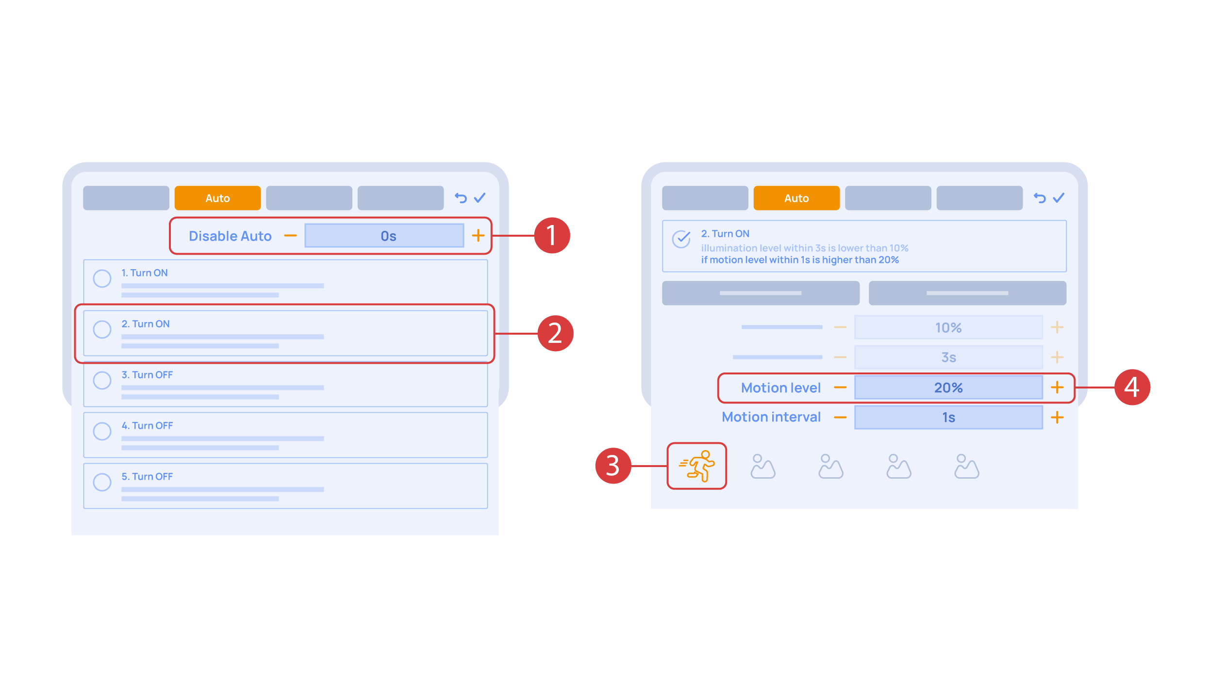
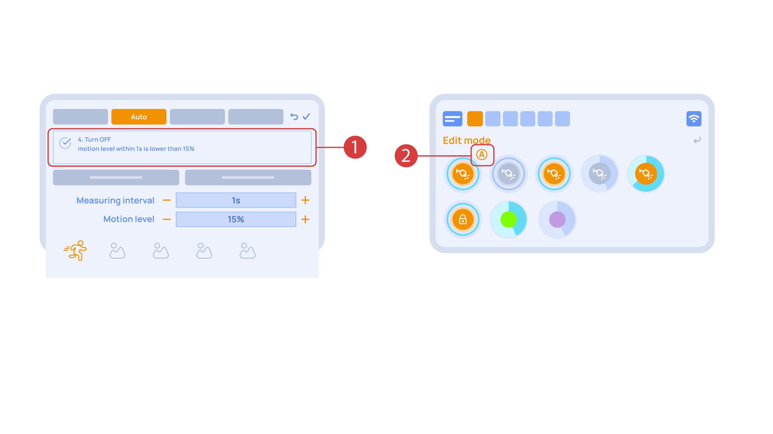
The ‘Auto period’ ① option sets the time for which the automation is disabled after an executor is manually controlled.For our demonstration purposes, we will set it to zero.
Then we will activate the automation ② to turn on the executor when motion is detected. We choose the motion sensor ③ and the level of motion ④. We can also choose a light sensor and its parameters.
Now we will activate turning off ① of an executor if there is no motion: we choose the same sensor, set a lower threshold and a minimal time.Save the changes.
The extra ‘A’ icon ② will be added to the executor icon, meaning that automation has been set up for it. Now the lamp will be turned on when motion is detected and instantly turned off when no motion is detected.
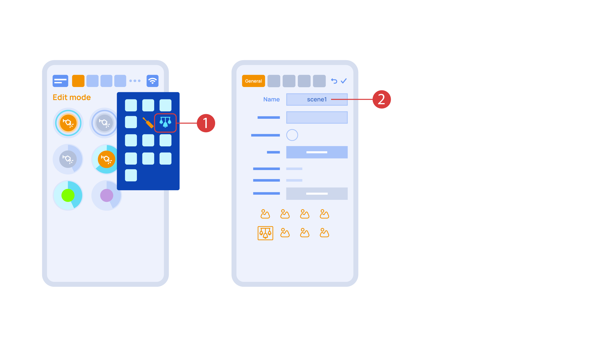
Let’s create a light scheme. For this we need to select the appropriate item in the additional menu ①. Give the light scheme a name ②.
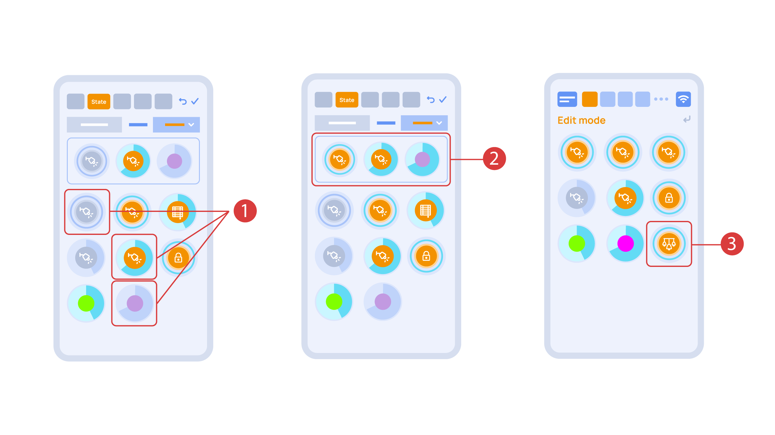
In the ‘State’ tab, use a long press to add the lights we want to use into the light scene ① and set up their state ②. ‘Auto’, ‘Schedule’, ‘Switch’ tabs are the same for all the executors.
Save the changes and we are able to use the newly-created light scheme ③ immediately.
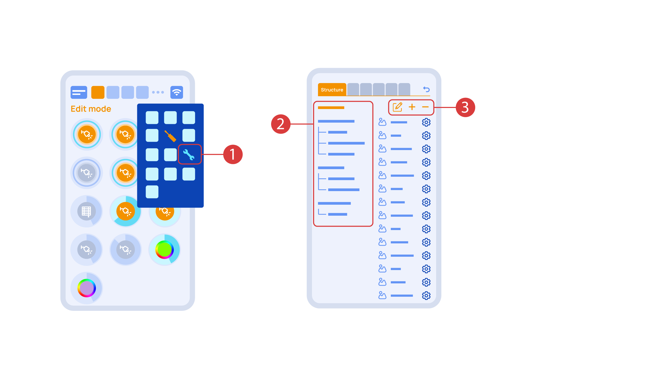
While you are in the Edit Mode, there is a ‘Setup’ ① icon in the additional menu.
Here in the ‘Structure’ ② tab we can see all the areas.
We can create new ones ③, rename them and move the elements around.
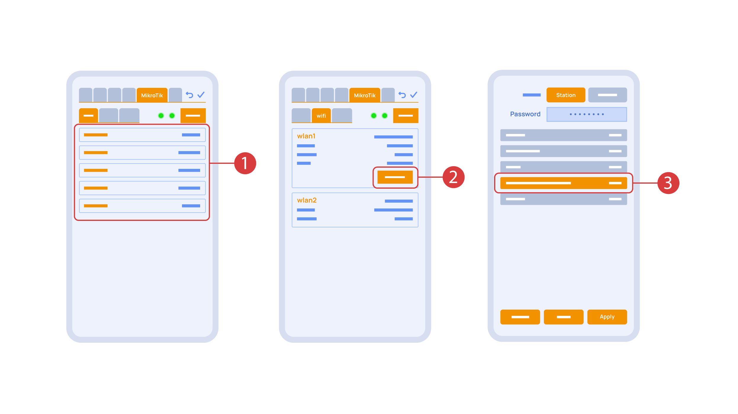
In the ‘Mikrotik’ tab ① you can see the current parameters of your router, which you can also connect to your local Wi-Fi network.
In order to do this, enter the Wi-Fi sub-menu, click the wlan1 interface configuration ②, after which choose the ‘station’ mode, choose a Wi-Fi network out of the list ③ of available ones and enter the connection password.
In the ‘Backups’ tab ① you can see the list of saved configurations, which can be restored if necessary.

For cloud access to the device, you do not need any extra settings. The app detects the absence of the system in your local network and automatically establishes the connection via the cloud.
We thank you for watching this tutorial! If you have questions or need extra help, please do not hesitate to refer to our technical support team. See you in the next episodes!