Краткое руководство
Быстрый старт/распаковка.
Приветствуем всех на нашем канале, данное видео посвящено обучению быстрой настройке системы Larnitech. Настройку мы будем производить на основе демонстрационного кейса. В комплект набора для обучения входит демонстрационный чемодан ① и коробок с дополнительными принадлежностями ②.
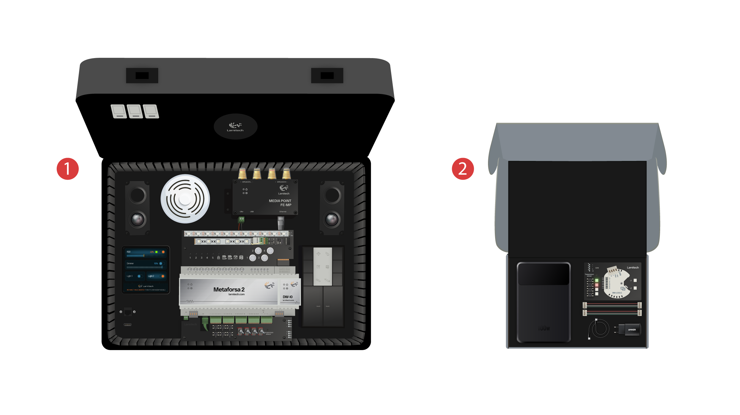
Внутри коробка вы найдете:
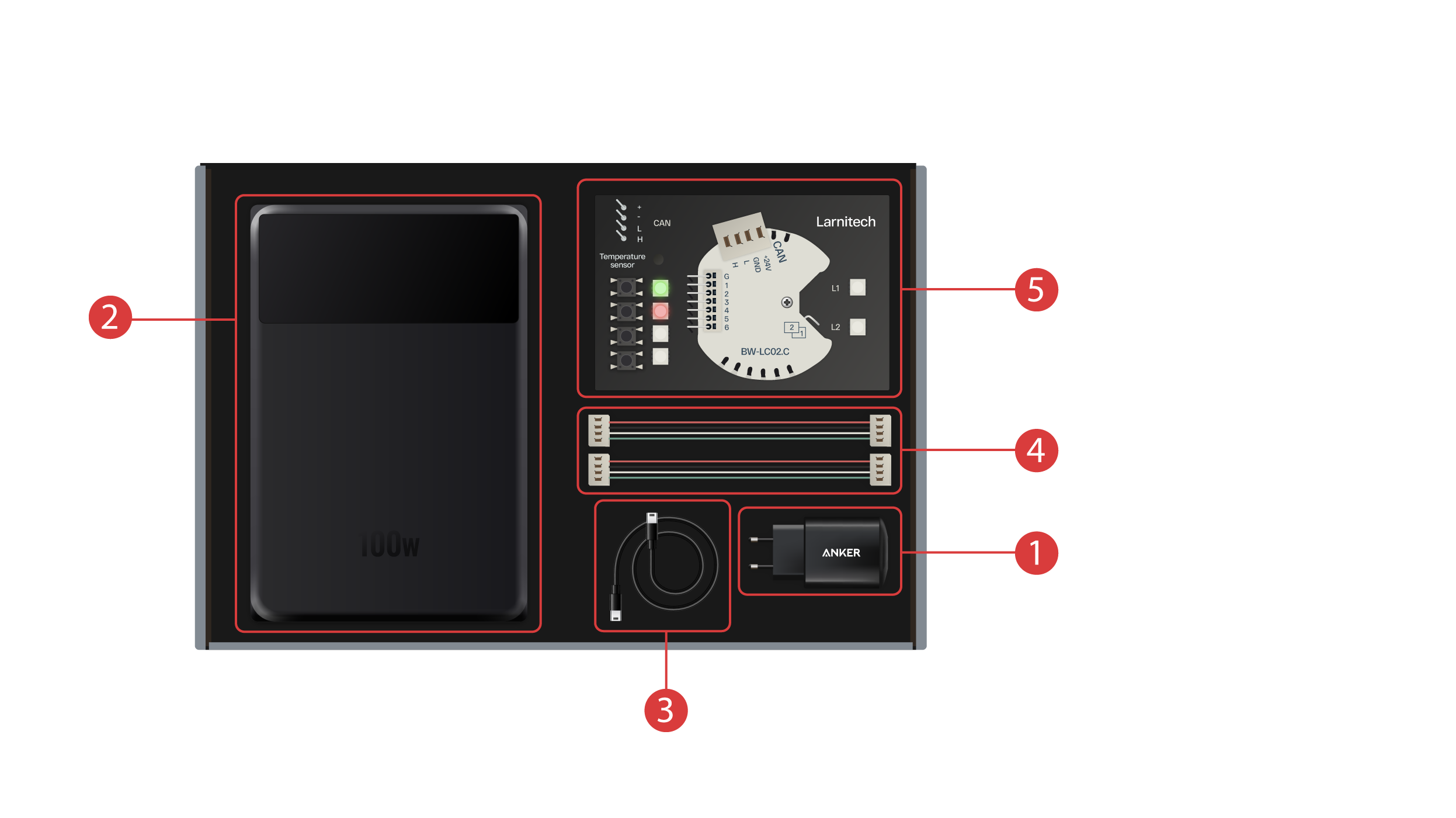
① - Блок питания с Type-C разъемом и поддержкой технологии Power Delivery;
② - Powerbank, оснащенный дисплеем и Type-C - выходом, способным питать демонстрационный чемодан;
③ - Кабель Type-C с индикацией потребляемой мощности;
④ - 2 кабеля CAN-шины;
⑤ - Демонстрационная плата с модулем BW-LC02, 2 светодиода, 4 кнопки с подсветкой и датчик температуры, подключенные к модулю.
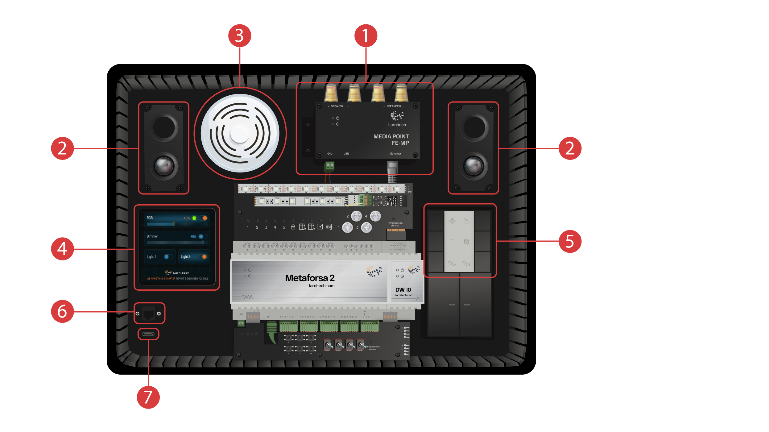
Демонстрационный чемодан содержит:
Модуль Metaforsa-2, который имеет:
① - 10 релейных выходов с подключенными светодиодами, которые отображают их текущее состояние;
② - 4 диммируемых канала, к которым подключены диммируемые светодиоды;
③ - 24 входа, к которым подключены 6 кнопок ④ и 4 переключателя ⑤ для имитации различных датчиков;
⑥ - Входы для подключения термодатчиков с одним подключенным датчиком;
⑦ - CAN-шина для дополнительных устройств, к которой подключены другие модули данного чемодана, а также 2 дополнительных порта ⑧ для внешних устройств.
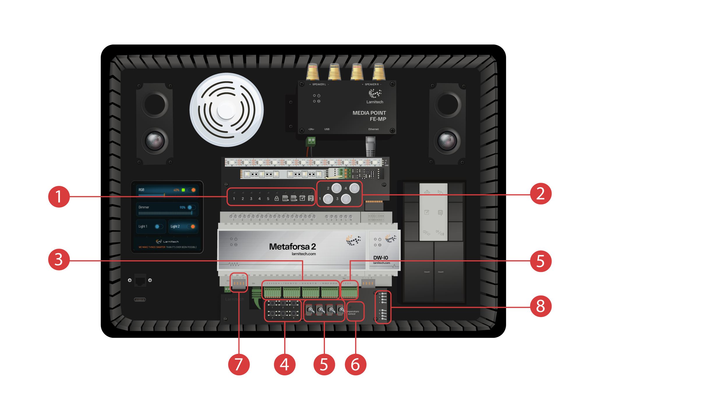
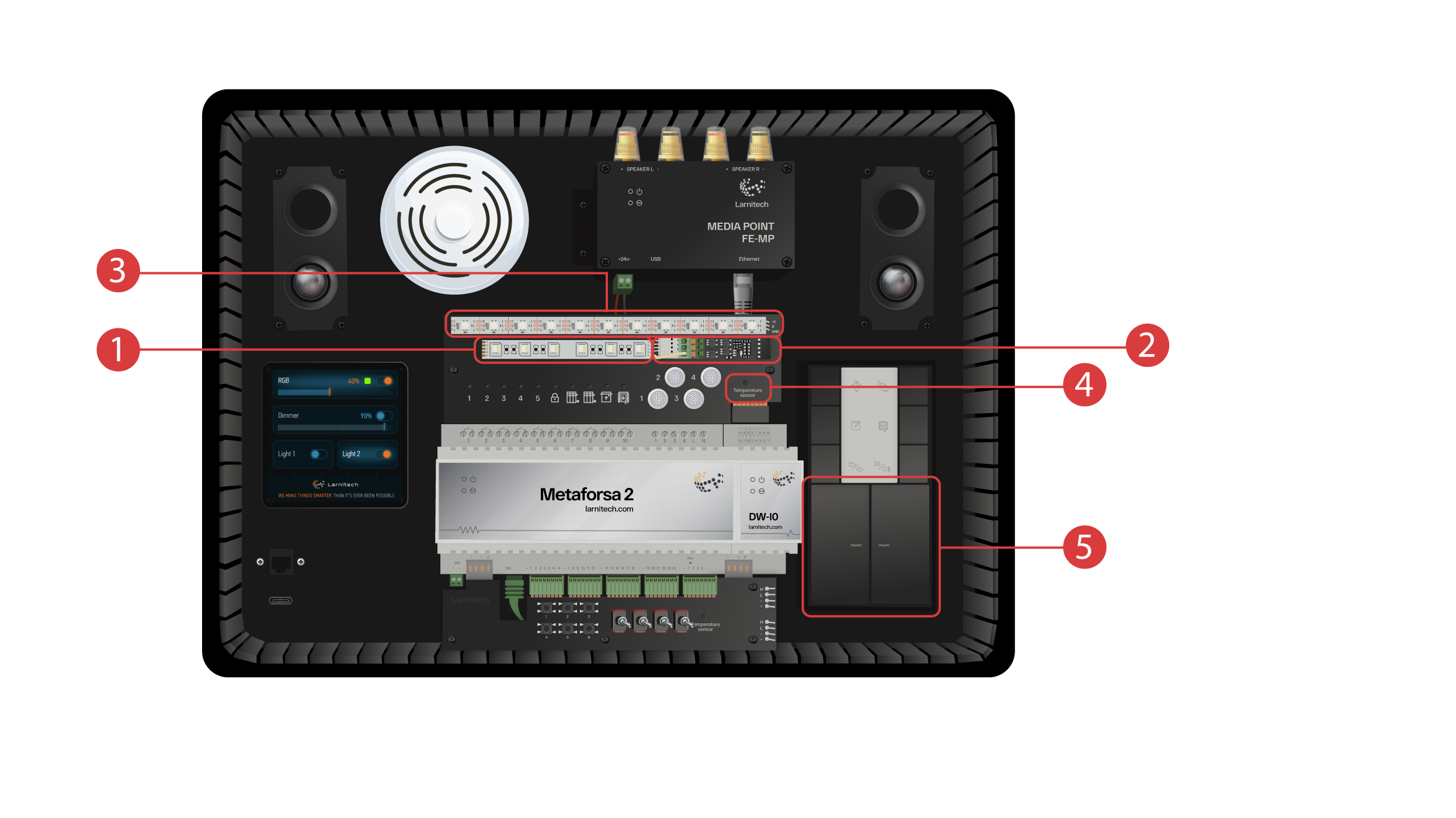
Модуль DW-IO
Этот модуль имеет 14 универсальных входов-выходов, к которым подключена:
① - 4х канальная RGBW-лента через усилитель тока AMP5V-4 ②;
③ - Лента с адресуемыми светодиодами, каждый из которых может отображать собственный цвет;
④ - Датчик температуры;
⑤ - И две клавиши с подсветкой.
Чемодан также содержит:
① - Медиаточку FE-MP с ② двумя динамиками;
③ - Датчик 6-в-1 CW-CO2 измеряющий: Уровень движения, Освещенности, Температуру, Влажность, Уровень углекислого газа, а также имеющий инфракрасный передатчик.
④ - 4-х дюймовая сенсорная панель LCP4, на которую можно вывести как обычный интерфейс, так и интерфейс, адаптированный для настенных панелей;
Внутри кейса также установлен модуль кнопок BW-SW24 , к которому подключена шестиклавишная 24-х-вольтовая панель фирмы JUNG ⑤.
А также wifi-роутер, который может подключаться к интернету либо через эзернет-порт ⑥, выведенный на переднюю панель, либо через имеющуюся wifi сеть.
Для питания на переднюю панель выведен Type-C-разъем ⑦.
Все оборудование, установленное в чемодане, питается от напряжения 20 Вольт, которое является безопасным.
Подключаем питание и Эзернет (позже мы продемонстрируем, как подключить внутренний роутер к вашей wifi-сети в случае, если у вас отсутствует возможность Ethernet-подключения).
Для дальнейшей работы вам потребуется установить приложение Larnitech на ваш смартфон или планшет. Для этого отсканируйте первый QR-код с крышки вашего чемодана.
Если после установки и запуска приложения подключение не произошло автоматически, то подключитесь с помощью вашего мобильного устройства к wifi-сети “Larnitech_case_5G”, затем запустите приложение и в отсканируйте первый QR-код в разделе “Соединения”.
Вам может также понадобиться отключить передачу данных на вашем мобильном устройстве, в случае, если демонстрационный набор не подключен к сети Internet.

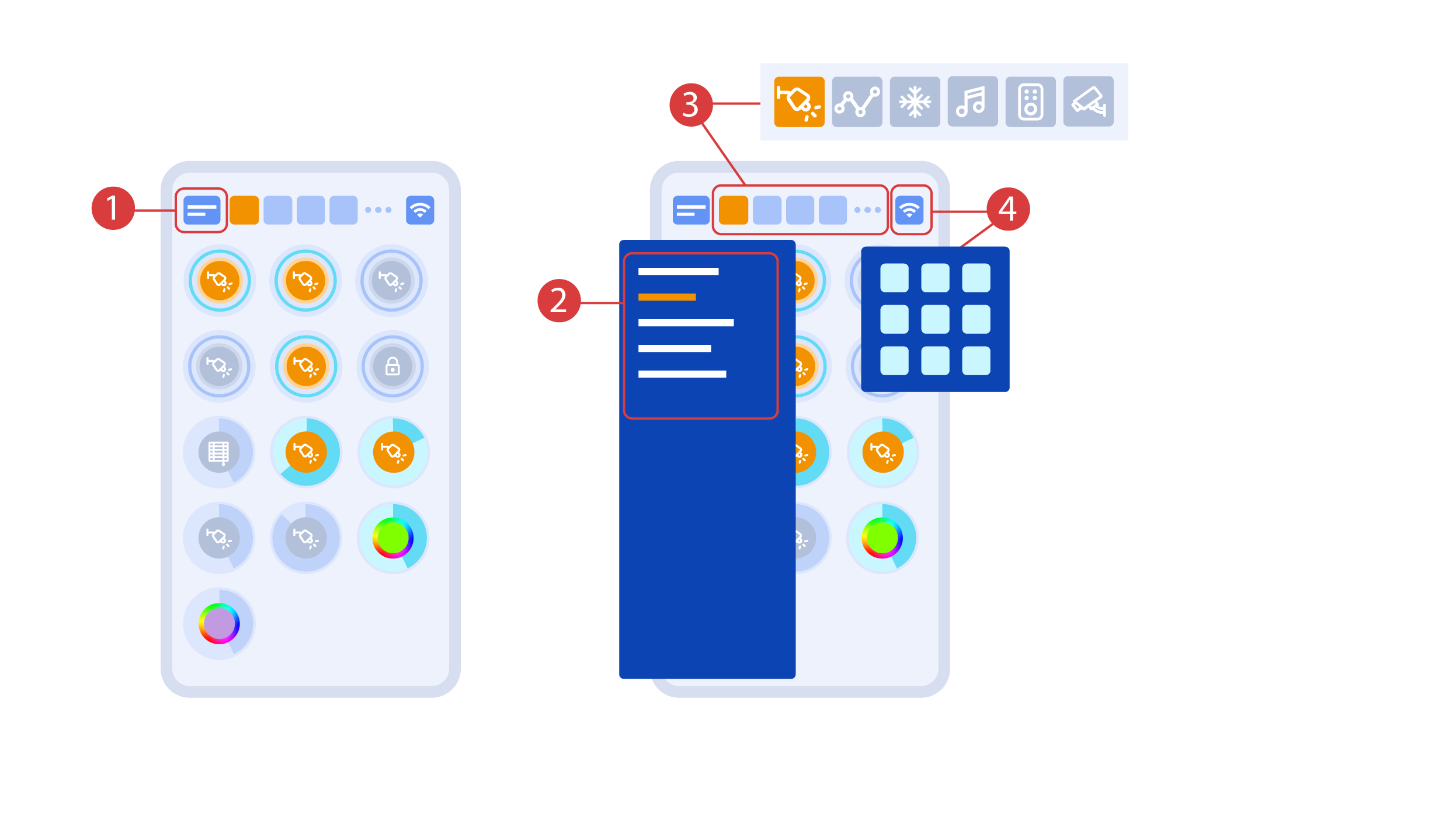
Основной экран приложения содержит несколько основных элементов. В верхнем левом углу располагается меню выбора помещения ①, нажав на которое, вы можете выбрать одно из доступных ②.
Далее располагаются иконки выбора исполнителей, датчиков, климата, мультимедиа, пульты дистанционного управления и камеры ③. В правом углу располагается иконка вызова дополнительного меню ④, внутри которой также отображается статус текущего соединения.
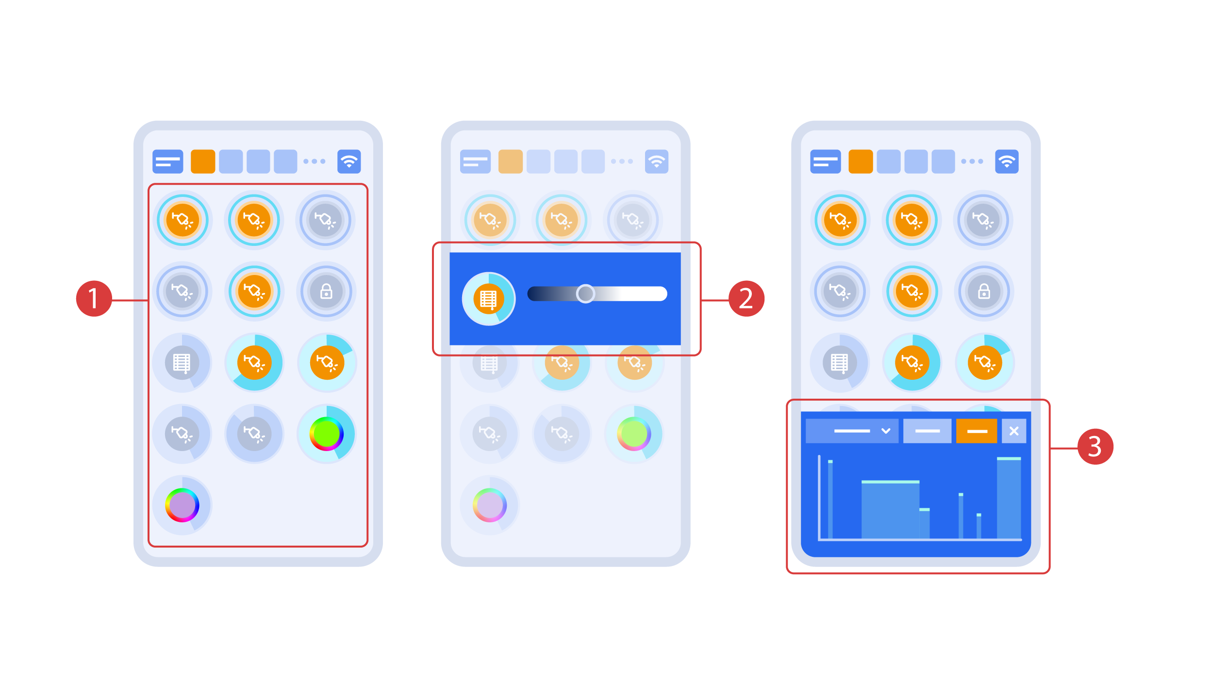
Включение/выключение исполнителей ① происходит простым нажатием, а для изменения уровня освещенности ②, цвета или выбора положения жалюзи воспользуйтесь двойным нажатием. Для отображения истории изменения состояния исполнителей или датчиков ③ нажмите на него и удерживайте в течении 1- ой секунды.
Короткое нажатие клавиш включает / выключает лампу, а удерживая клавишу, вы можете изменять ее яркость.
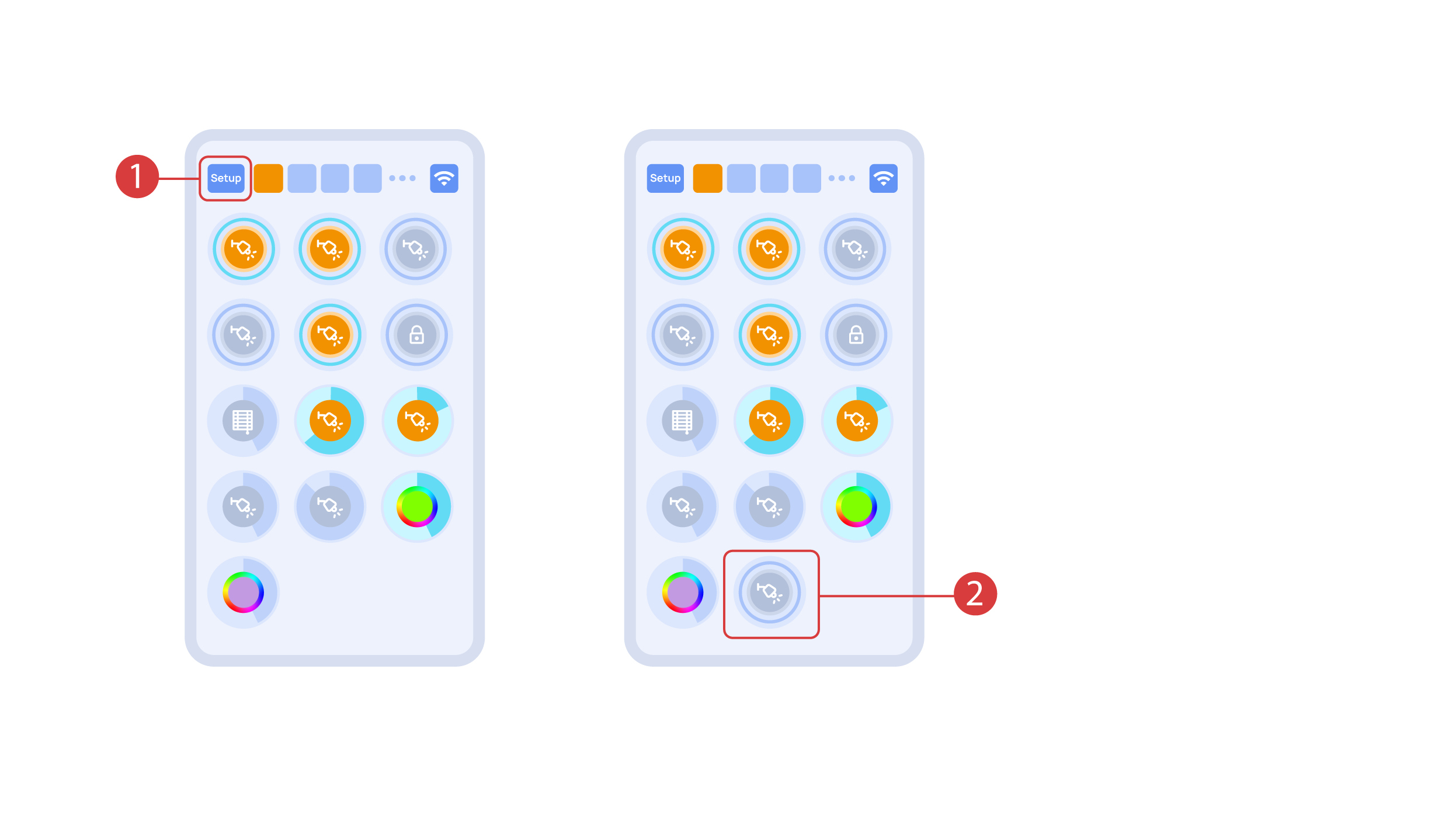
In order to demonstrate the Plug and Play function, we open the executors in the Setup area ① and connect the module to the CAN bus. The system automatically detects the new module and adds it to the ‘Setup’ area, ② where we are able to control the new module instantly.
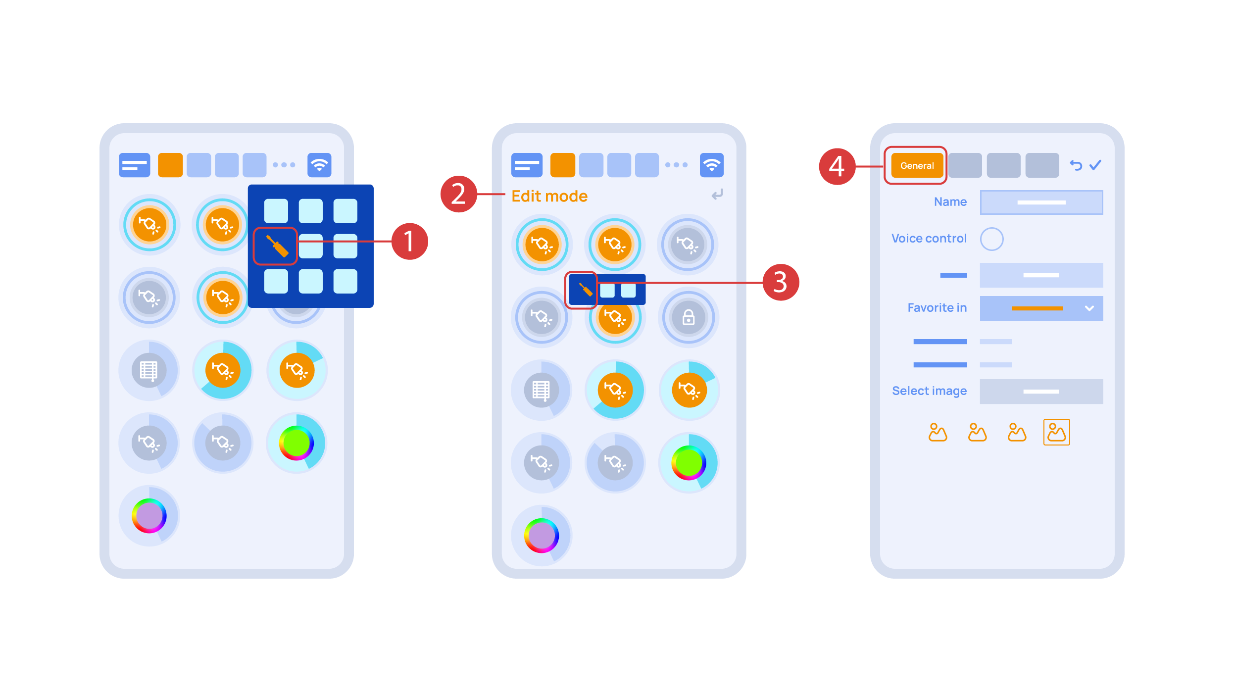
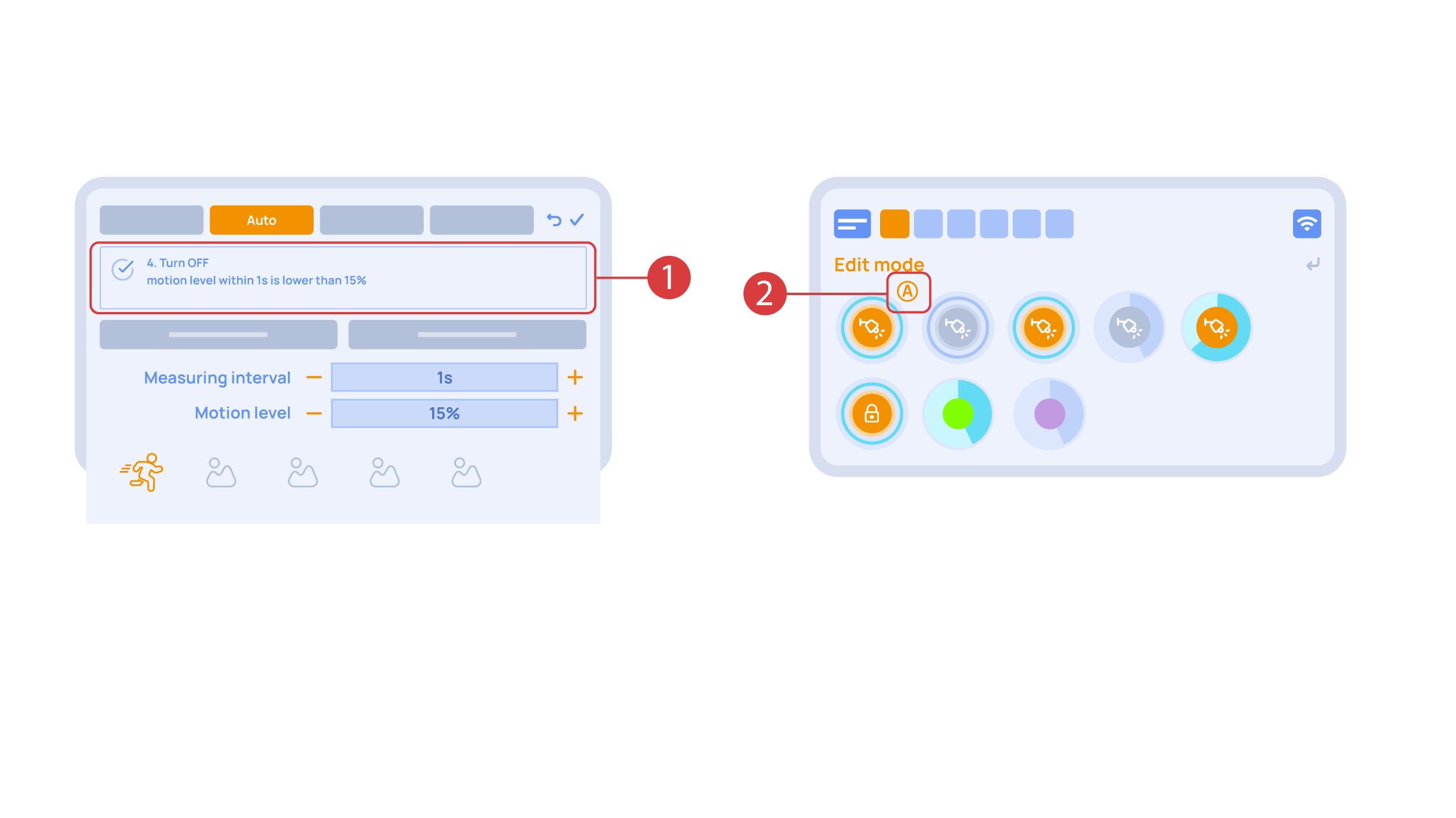
Now we can set up these executors. In order to do this, enter the additional menu ① and activate the edit mode, by pressing the appropriate icon .
Now we are in the edit mode ②, which can be seen from the appropriate notification in the top part of the screen. In this mode, when we press and hold an icon, we can move it among other elements and place it into another Room by placing it in the Area-choosing Menu and then choosing the area that we need. A long press ③ of the element starts the menu, from which we set up the current element.In the ‘General’ ④ section we can change the name of the element, add a voice command for it, change an icon or add the element to ‘Favorites’.
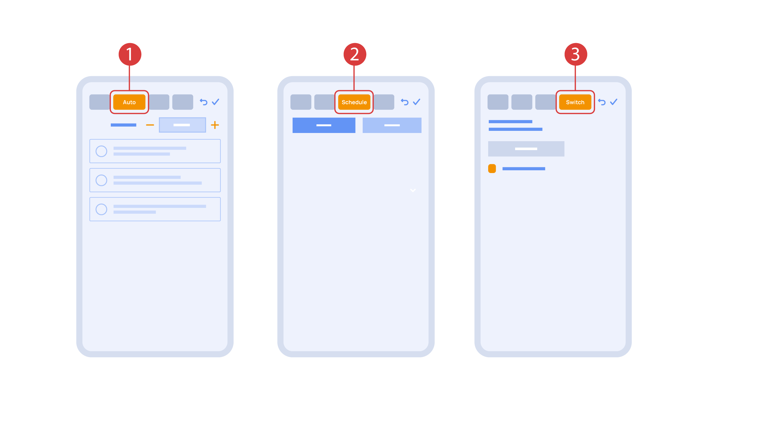
‘Auto’ section ① lets us activate the automation with a few clicks, as well as set up its parameters.
In the ‘schedule’ section ②, you can determine the schedule when the given element will turn on or off, including by using the time of the setting and rising of the sun.
The ‘Switches’ tab ③ lets you bind a button to control the executor.
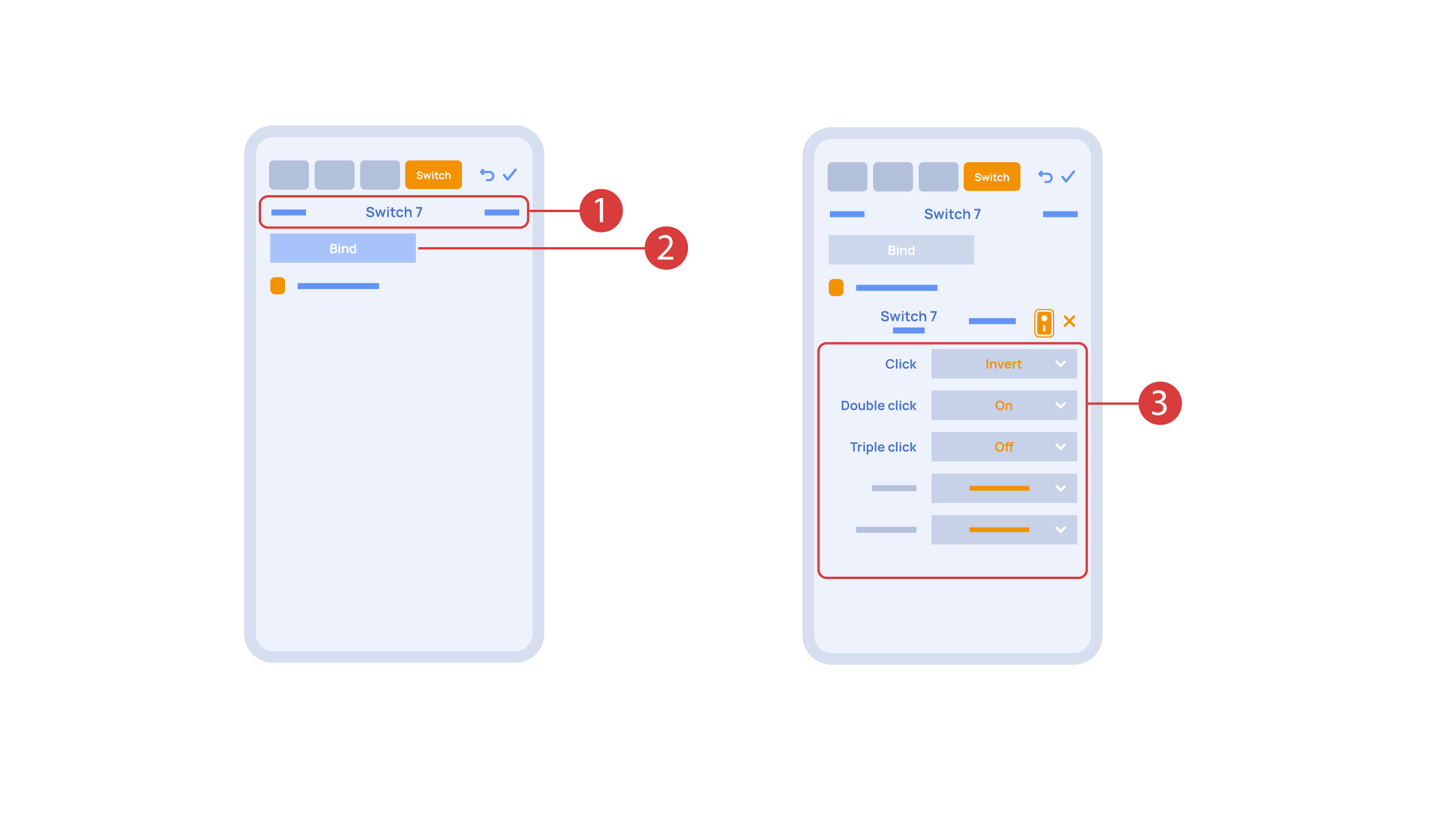
In order to do this, ① we press the button we need to bind. The system displays it, after which we press ‘Bind’② and save the changes. Now this button controls the executor
The ‘Switches’ tab ③ also features additional button setup options. For example, we can program the executor to be controlled with a double or triple click of a button, as well as define an action performed by this, for example ‘only turning on’ or ‘only turning off’ an executor. In this case we are setting up the button to do the following: one click will cause the lamp to toggle, a double click will turn it on and a triple click will turn it off. In this way a single button can perform up to five different actions.
Let’s also set up basic automation of turning an executor on or off with the help of a motion sensor.
The ‘Auto period’ ① option sets the time for which the automation is disabled after an executor is manually controlled.For our demonstration purposes, we will set it to zero.
Then we will activate the automation ② to turn on the executor when motion is detected. We choose the motion sensor ③ and the level of motion ④. We can also choose a light sensor and its parameters.
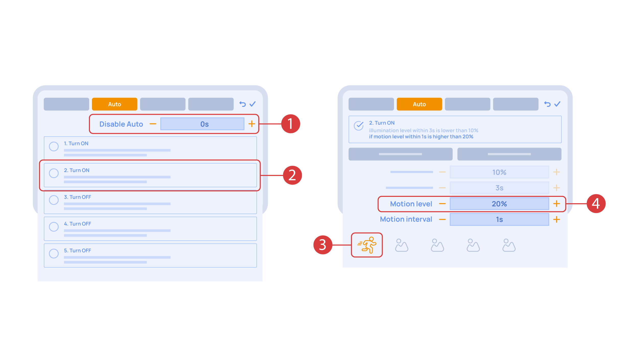
Now we will activate turning off ① of an executor if there is no motion: we choose the same sensor, set a lower threshold and a minimal time.Save the changes.
The extra ‘A’ icon ② will be added to the executor icon, meaning that automation has been set up for it. Now the lamp will be turned on when motion is detected and instantly turned off when no motion is detected.
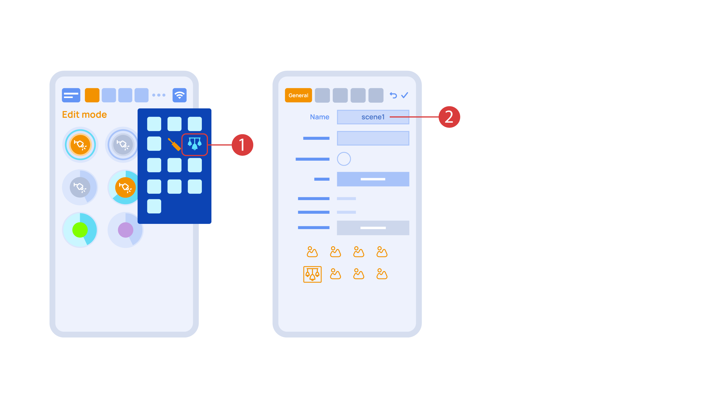
Let’s create a light scheme. For this we need to select the appropriate item in the additional menu ①. Give the light scheme a name ②.
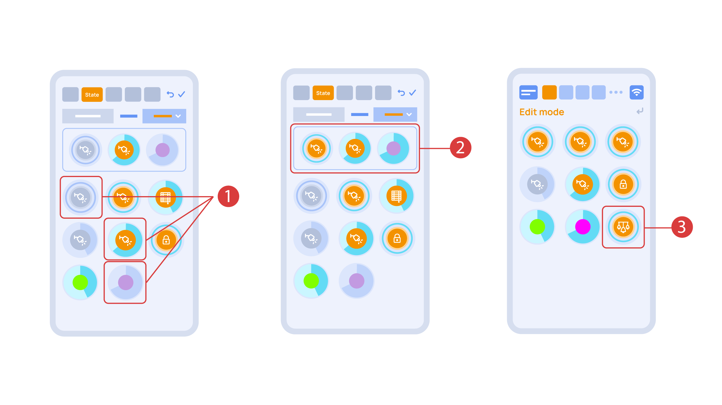
In the ‘State’ tab, use a long press to add the lights we want to use into the light scene ① and set up their state ②. ‘Auto’, ‘Schedule’, ‘Switch’ tabs are the same for all the executors.
Save the changes and we are able to use the newly-created light scheme ③ immediately.
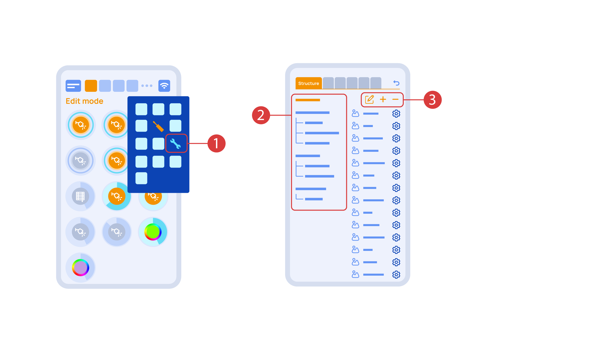
While you are in the Edit Mode, there is a ‘Setup’ ① icon in the additional menu.
Here in the ‘Structure’② tab we can see all the areas.
We can create new ones ④, rename them and move the elements around.
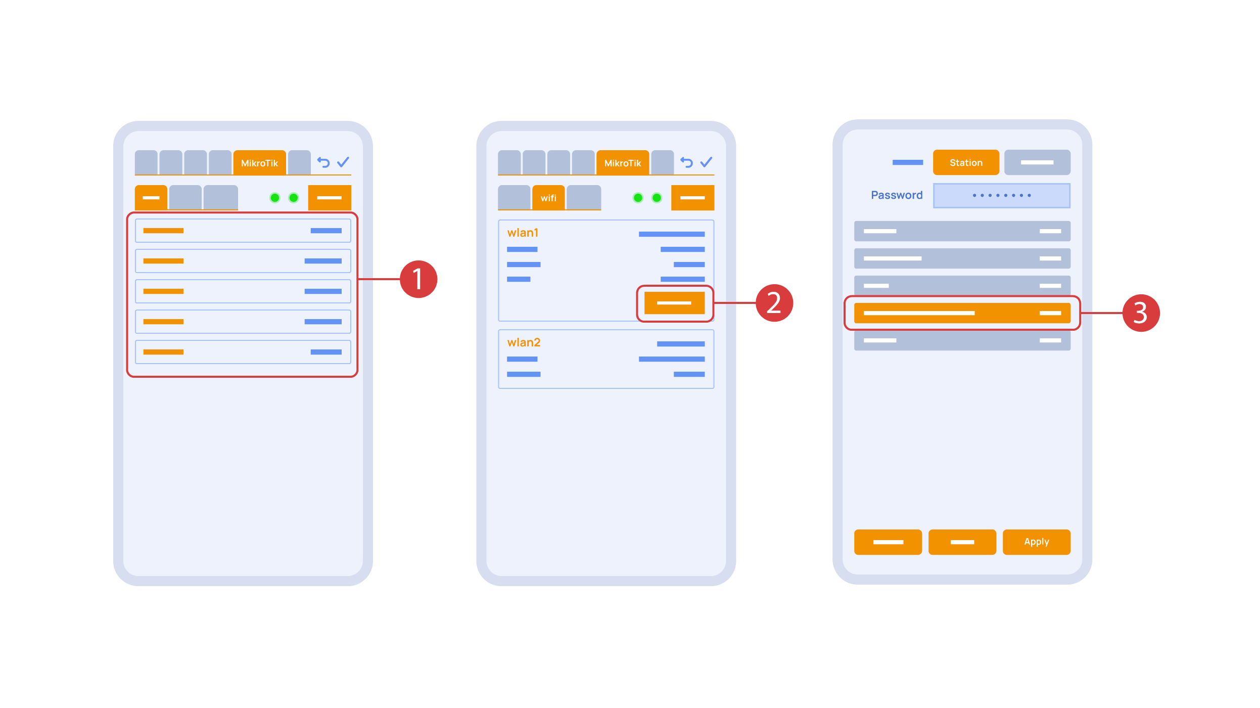
In the ‘Mikrotik’ tab ① you can see the current parameters of your router, which you can also connect to your local Wi-Fi network.
In order to do this, enter the Wi-Fi sub-menu, click the wlan1 interface configuration ②, after which choose the ‘station’ mode, choose a Wi-Fi network out of the list ③ of available ones and enter the connection password.
In the ‘Backups’ tab ① you can see the list of saved configurations, which can be restored if necessary.

For cloud access to the device, you do not need any extra settings. The app detects the absence of the system in your local network and automatically establishes the connection via the cloud.
We thank you for watching this tutorial! If you have questions or need extra help, please do not hesitate to refer to our technical support team. See you in the next episodes!