Посібник із швидкого початку роботи
Швидкий старт/розпакування.
Вітаємо всіх на нашому каналі, це відео присвячене навчанню швидкого налаштування системи
Larnitech (ЛарнітЕх). Налаштування ми будемо робити на основі демонстраційного кейсу.
У комплект набору для навчання входить демонстраційна валіза ① та коробки з додатковим приладдям ②.
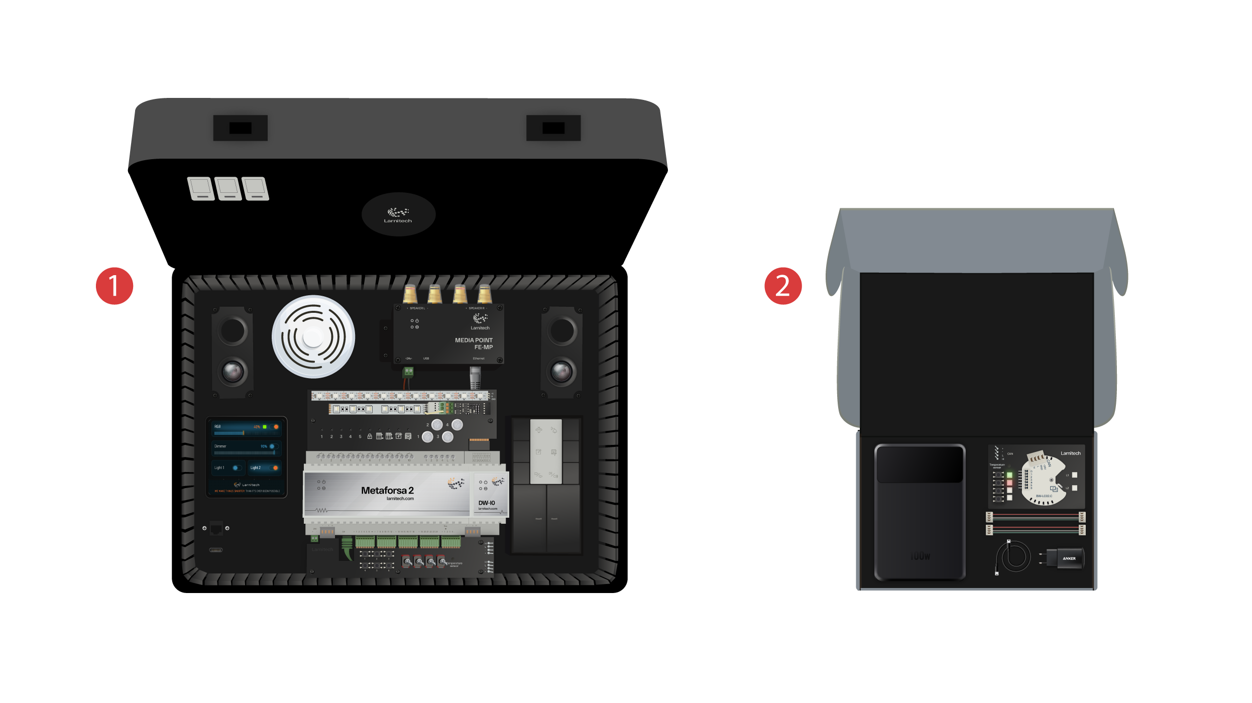
Усередині коробки ви знайдете:
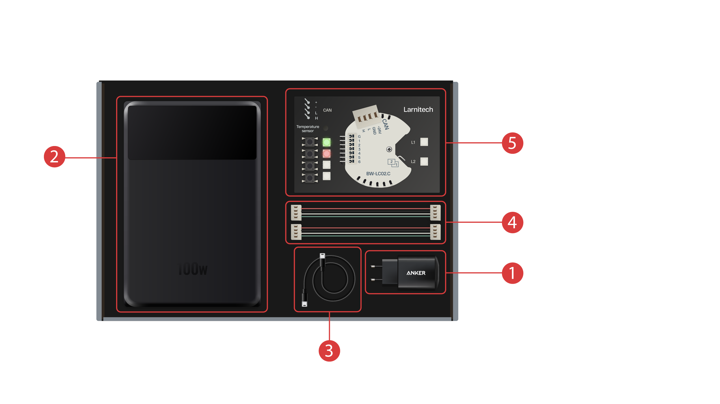
① - Блок живлення з Type-C (тайп-сі) роз'ємом та підтримкою технології Power Delivery (пАуер делІвері);
② - Powerbank (пАуер банк), оснащений дисплеєм і Type-C-(тайп-сі) - виходом, здатним живити демонстраційну валізу;
③ - TКабель Type-C (тайп-сі) з індикацією споживаної потужності;
④ - 2 кабелі CAN-шини (кан-шини);
⑤ - Демонстраційна плата з модулем BW-LC-02 (бі.дабл.ю-ел.синоль два), 2 світлодіоди, 4 кнопки з підсвічуванням та датчик температури, підключені до модуля.
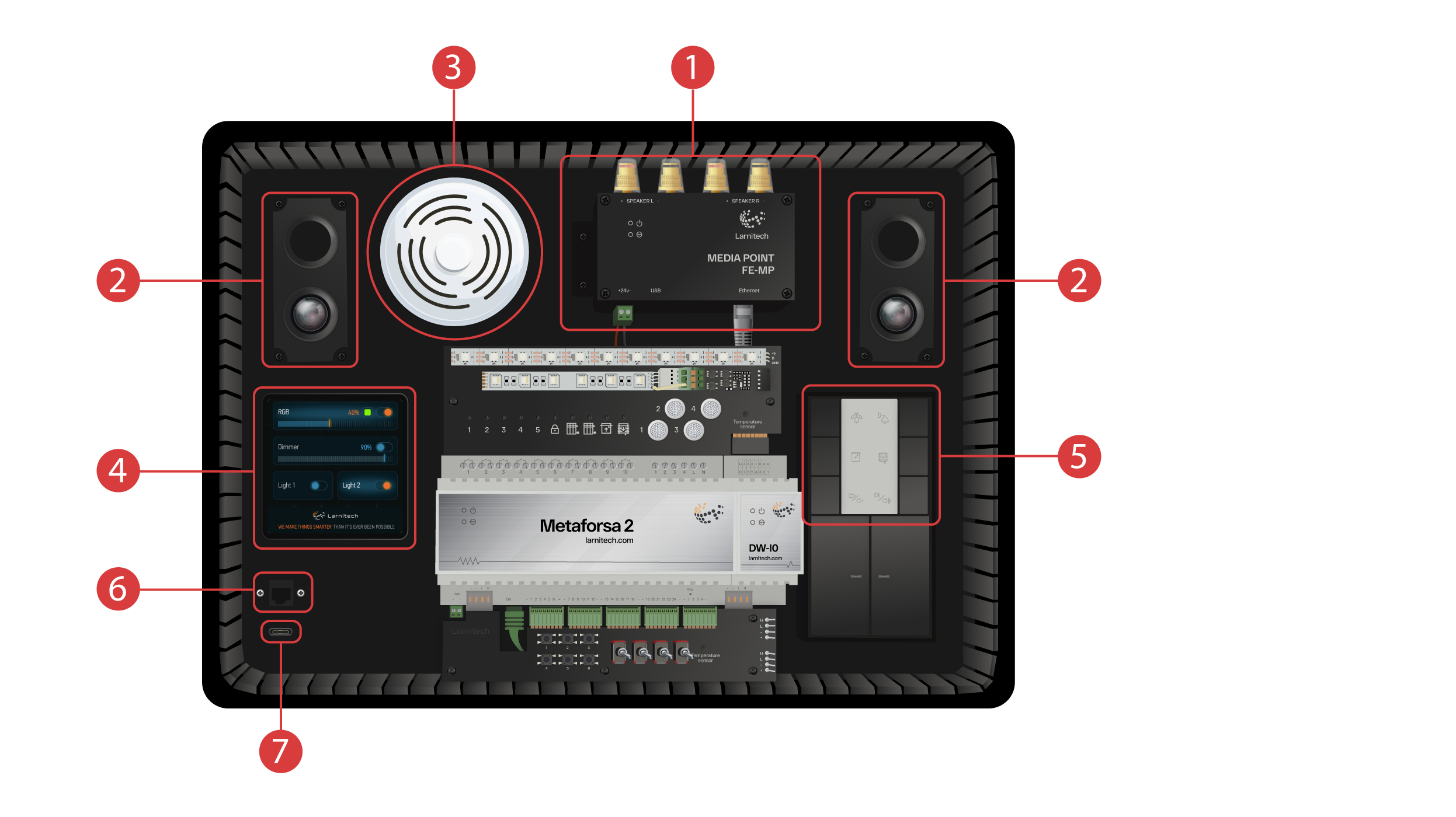
Демонстраційна валіза містить:
Модуль Metaforsa-2 (метафОрса-два), який має:
① - 10 релейних виходів із підключеними світлодіодами, які відображають їх поточний стан;
② - 4 димовані канали, до яких підключені димовані світлодіоди;
③ - 24 входи, до яких підключено 6 кнопок ④ і 4 перемикачі ⑤ для імітації різних датчиків;
⑥ - Входи для підключення термодатчиків з одним підключеним датчиком;
⑦ - CAN-шина (кан-Шина) для додаткових пристроїв, до якої підключені інші модулі цієї валізи, а також 2 додаткові порти ⑧ для зовнішніх пристроїв;
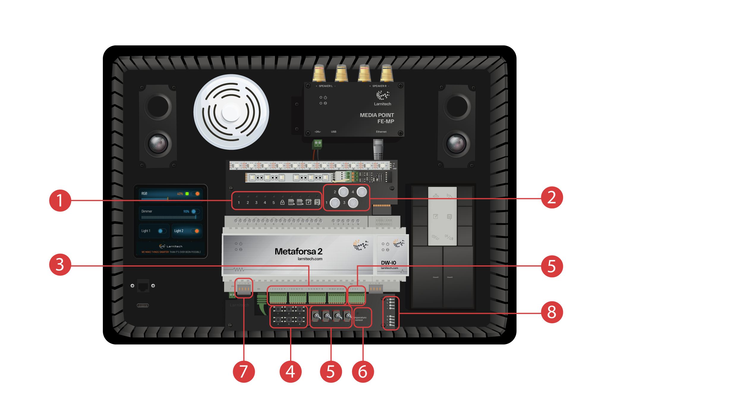
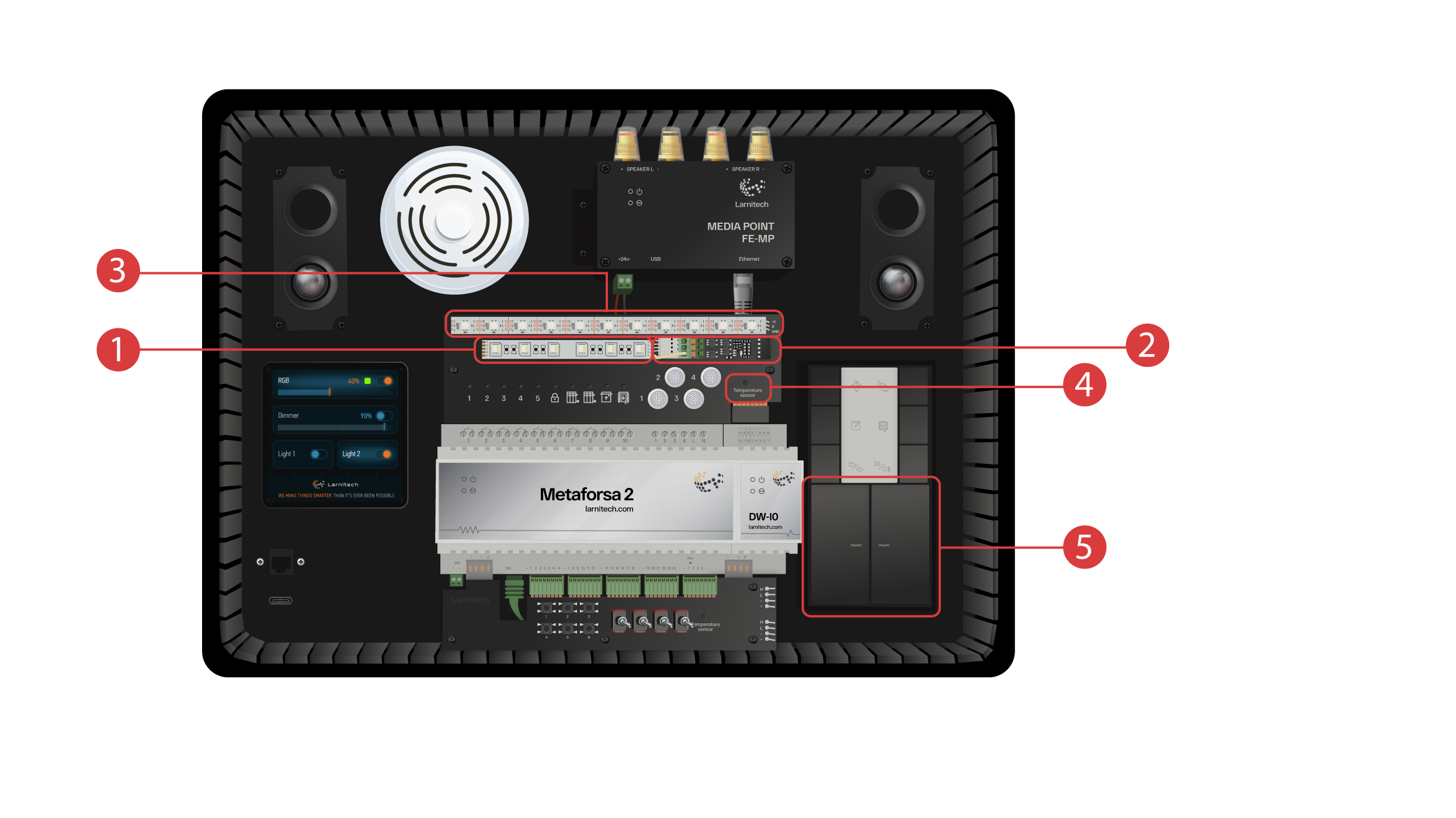
Модуль DW-IO (ді.дабл.ю-ай.оу.)
Цей модуль має 14 універсальних входів-виходів, до яких підключено:
① - 4х канальну RGBW-стрічку (ар.джи.бі.дабл.ю-стрічку) підключену через підсилювач струму AMP5V-4 (емп п'ять ві чотири) ② ;
③ - Стрічка з адресуємимі світлодіодами, кожен з яких може відображати власний колір;
④ - Датчик температури;
⑤ - І дві клавіші з підсвічуванням.
Демонстраційник кейс також містить:
① - Медіаточка FE-MP (еф. та - ем.пі) з ② двома динаміками;
③ - Датчик 6-в-1 CW-CO2 (сі.дабл.ю-цеодва) що вимірює: Рівень руху, Освітленості, Темпаратуру, Вологість, Рівень вуглекислого газу, а також має інфрачервоний передавач.
④ - 4-дюймова сенсорна панель LCP4 (ел.сі.пі.чотири), на яку можна вивести як звичайний інтерфейс, а також інтерфейс, адаптований для настінних панелей;
Всередині кейсу також встановлено модуль кнопок BW-SW24 (бі.дабл.ю-ес.дабл.ю двадцять чотири) ⑤, до якого підключено шестиклавішну 24-вольтову панель фірми JUNG (юнг).
А також wifi-роутер, який може підключатися до інтернету або через езернет-порт ⑥, виведений на передню панель, або через наявну мережу wifi.
Для живлення на виведено Type-C (тайп-сі)-роз'єм. ⑦, що знаходиться на паредній панелі.
Все обладнання, встановлене у валізі, живиться від напруги 20 Вольт, яке є безпечним.
Підключаємо живлення та Езернет (пізніше ми продемонструємо, як підключити внутрішній роутер до вашої wifi-мережі у разі, якщо у вас відсутня можливість Ethernet (езернет)-підключення).
Для подальшої роботи вам потрібно встановити додаток Larnitech (ЛарнітЕх) на ваш смартфон або планшет. Для цього відскануйте перший QR(кью.ар)-код із кришки вашої валізи.
Якщо після встановлення та запуску додатоку з'єднання не відбулося автоматично, то підключіться за допомогою вашого мобільного пристрою до wifi-мережі “Larnitech_case_5G” (ЛарнітЕх-кейс п'ять джі), потім запустіть додаток і відскануйте перший QR-код у розділі “з'єднання”. Вам можливо також буде потрібно вимкнути передачу даних на вашому мобільному пристрої, якщо демонстраційний кейс не підключено до мережі Internet (інтернет).

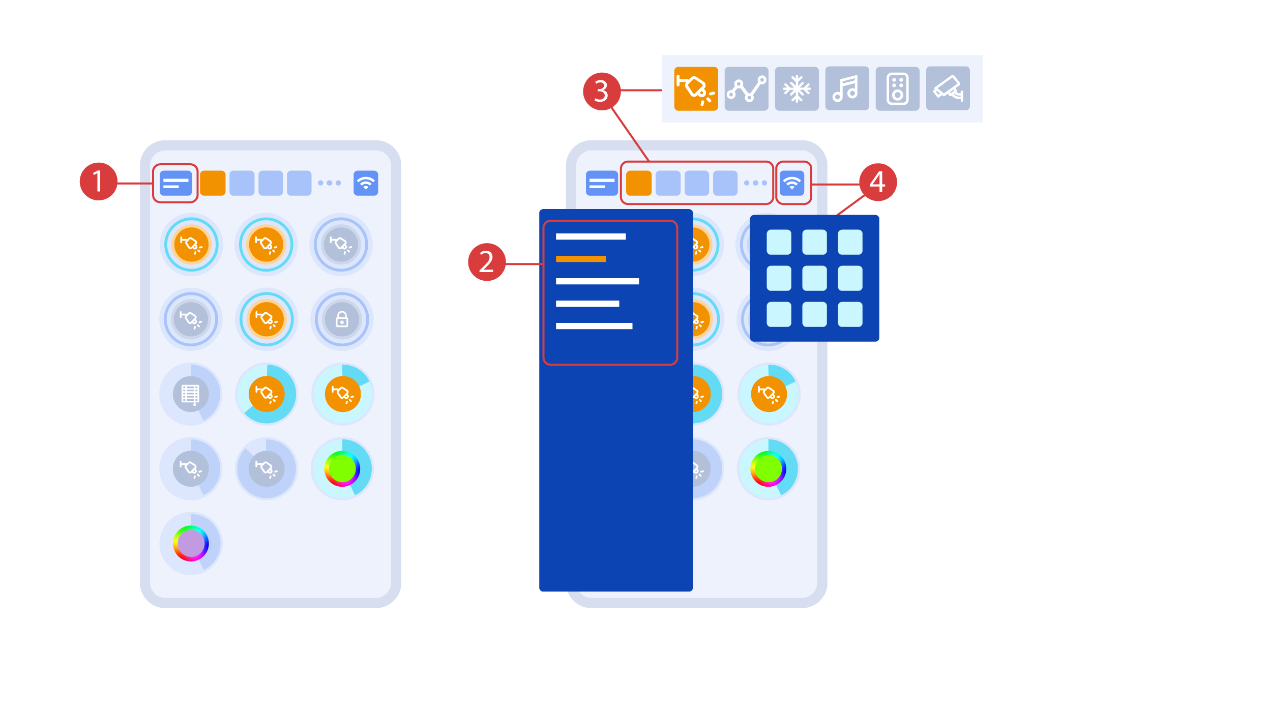
Основний екран містить кілька основних елементів. У верхньому лівому кутку розташовується меню вибору приміщення ①,
натиснувши на яке, ви можете обрати одне з доступних ②.
Далі розташовуються іконки вибору виконавців, датчиків, клімату, мультимедіа, пульти дистанційного керування та камери ③. У правому кутку розташовується іконка виклику додаткового меню ④, всередині якої також відображається статус поточного з'єднання.
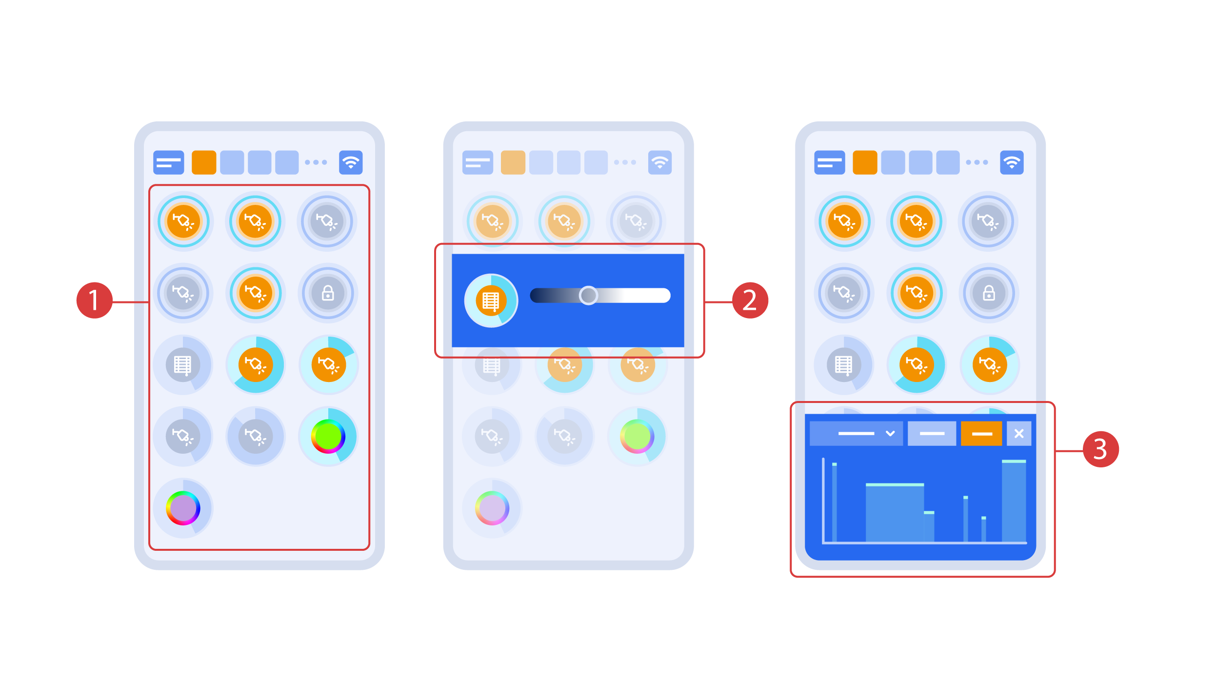
Turning the executors ① on or off is done with a simple click. In order to change the level of lighting ②, color of lights or the position of the blinds, use a double click. In order to access the status history ③ of this executor or sensor, press and hold the icon for one second.
A short press of the physical buttons on the panel turns the light on or off. Press and hold the button to change the light brightness.
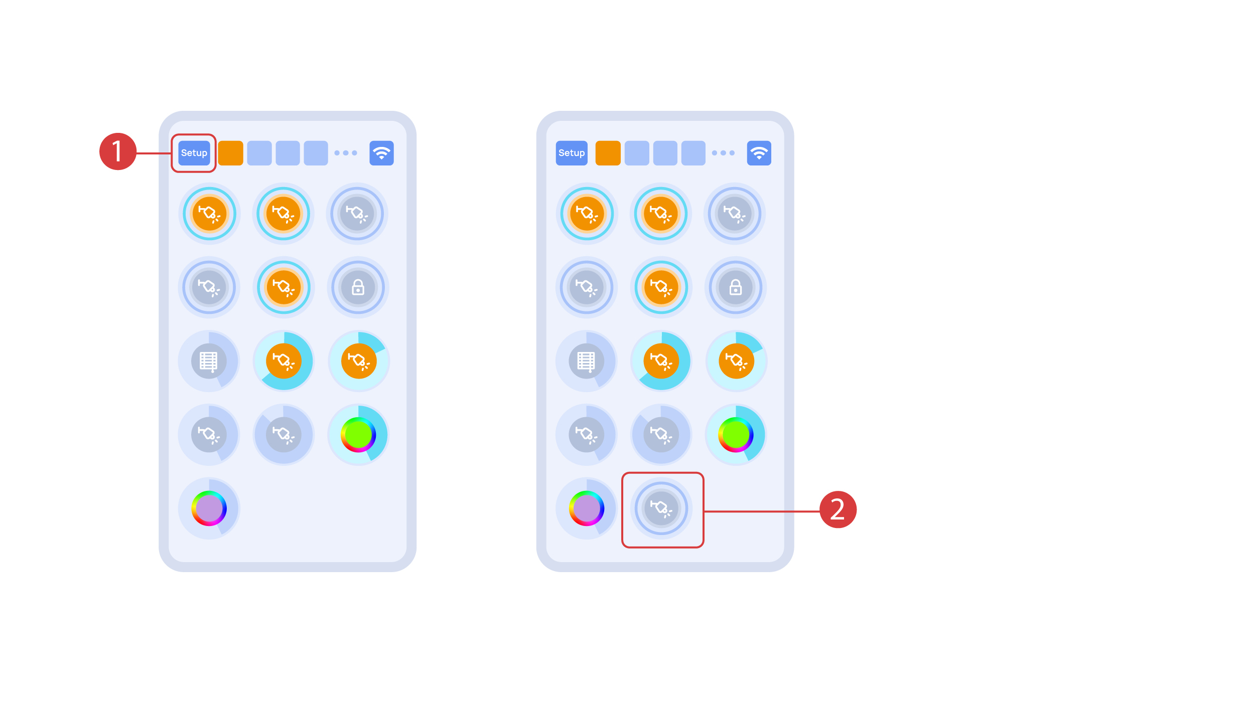
In order to demonstrate the Plug and Play function, we open the executors in the Setup area ① and connect the module to the CAN bus. The system automatically detects the new module and adds it to the ‘Setup’ area, ② where we are able to control the new module instantly.
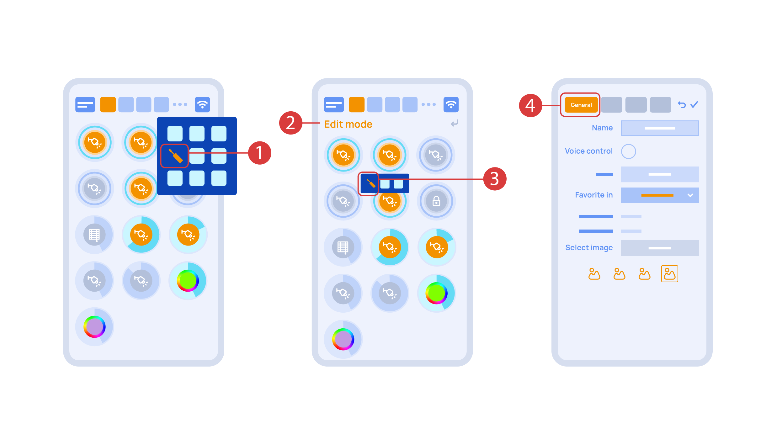
Now we can set up these executors. In order to do this, enter the additional menu ① and activate the edit mode, by pressing the appropriate icon .
Now we are in the edit mode ②, which can be seen from the appropriate notification in the top part of the screen. In this mode, when we press and hold an icon, we can move it among other elements and place it into another Room by placing it in the Area-choosing Menu and then choosing the area that we need. A long press ③ of the element starts the menu, from which we set up the current element.In the ‘General’ ④ section we can change the name of the element, add a voice command for it, change an icon or add the element to ‘Favorites’.
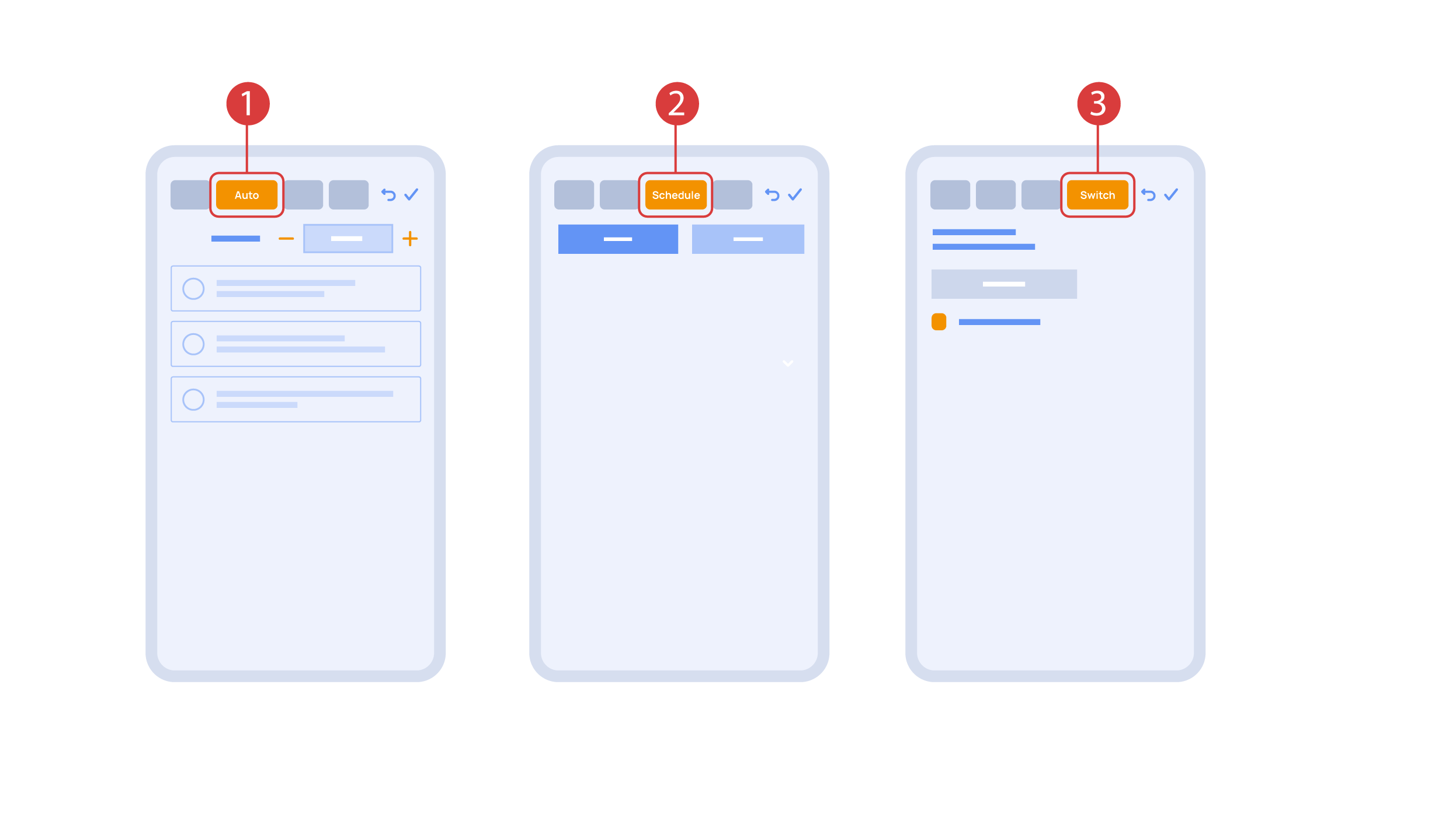
‘Auto’ section ① lets us activate the automation with a few clicks, as well as set up its parameters.
In the ‘schedule’ section ②, you can determine the schedule when the given element will turn on or off, including by using the time of the setting and rising of the sun.
The ‘Switches’ tab ③ lets you bind a button to control the executor.
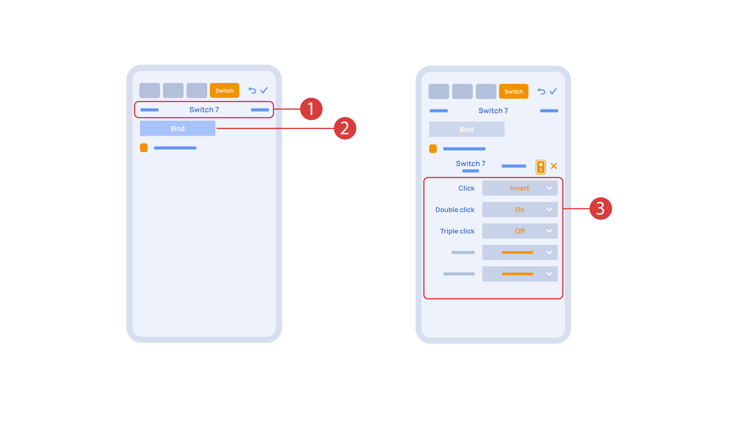
In order to do this, ① we press the button we need to bind. The system displays it, after which we press ‘Bind’② and save the changes. Now this button controls the executor
The ‘Switches’ tab ③ also features additional button setup options. For example, we can program the executor to be controlled with a double or triple click of a button, as well as define an action performed by this, for example ‘only turning on’ or ‘only turning off’ an executor. In this case we are setting up the button to do the following: one click will cause the lamp to toggle, a double click will turn it on and a triple click will turn it off. In this way a single button can perform up to five different actions.
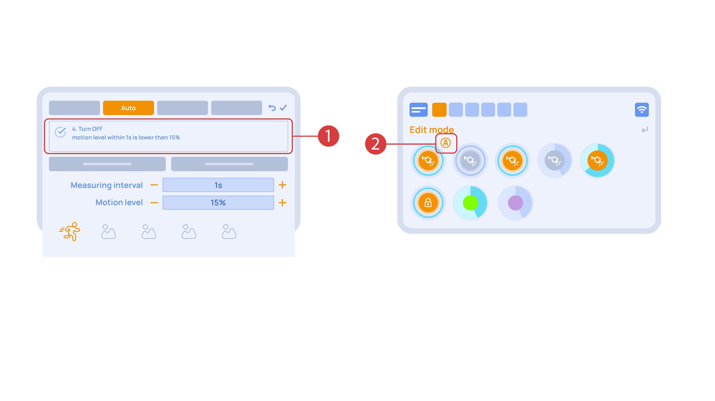
Let’s also set up basic automation of turning an executor on or off with the help of a motion sensor.
The ‘Auto period’ ① option sets the time for which the automation is disabled after an executor is manually controlled.For our demonstration purposes, we will set it to zero.
Then we will activate the automation ② to turn on the executor when motion is detected. We choose the motion sensor ③ and the level of motion ④. We can also choose a light sensor and its parameters.
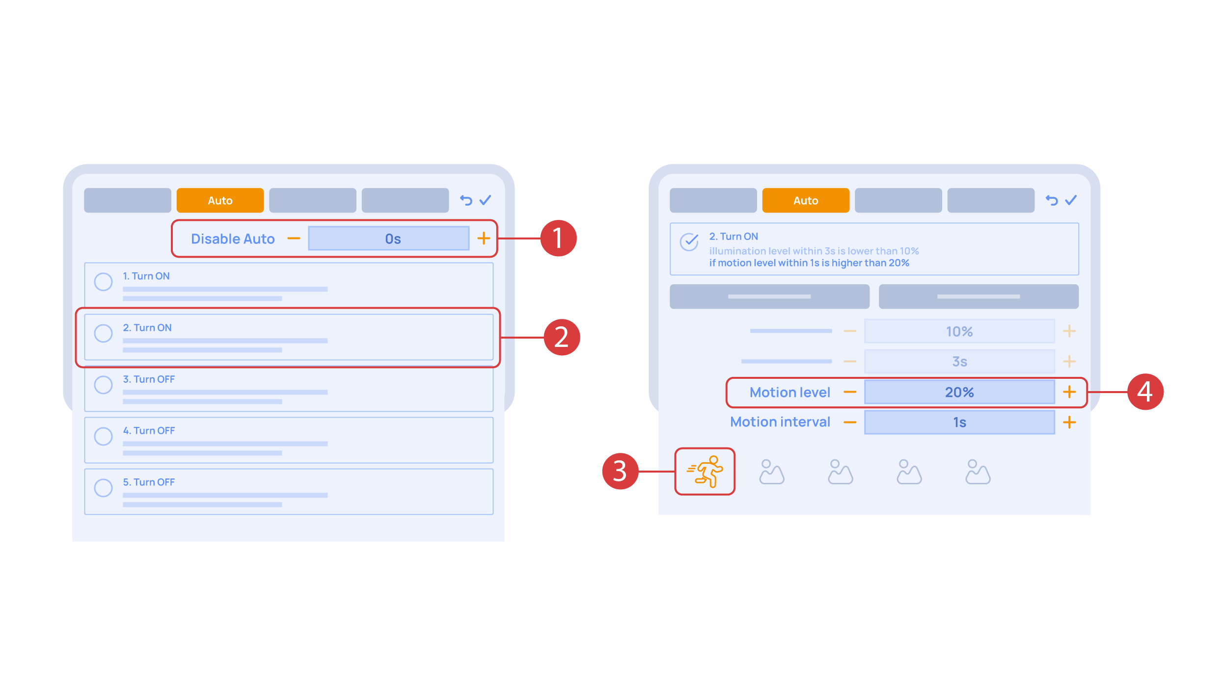
Now we will activate turning off ① of an executor if there is no motion: we choose the same sensor, set a lower threshold and a minimal time.Save the changes.
The extra ‘A’ icon ② will be added to the executor icon, meaning that automation has been set up for it. Now the lamp will be turned on when motion is detected and instantly turned off when no motion is detected.
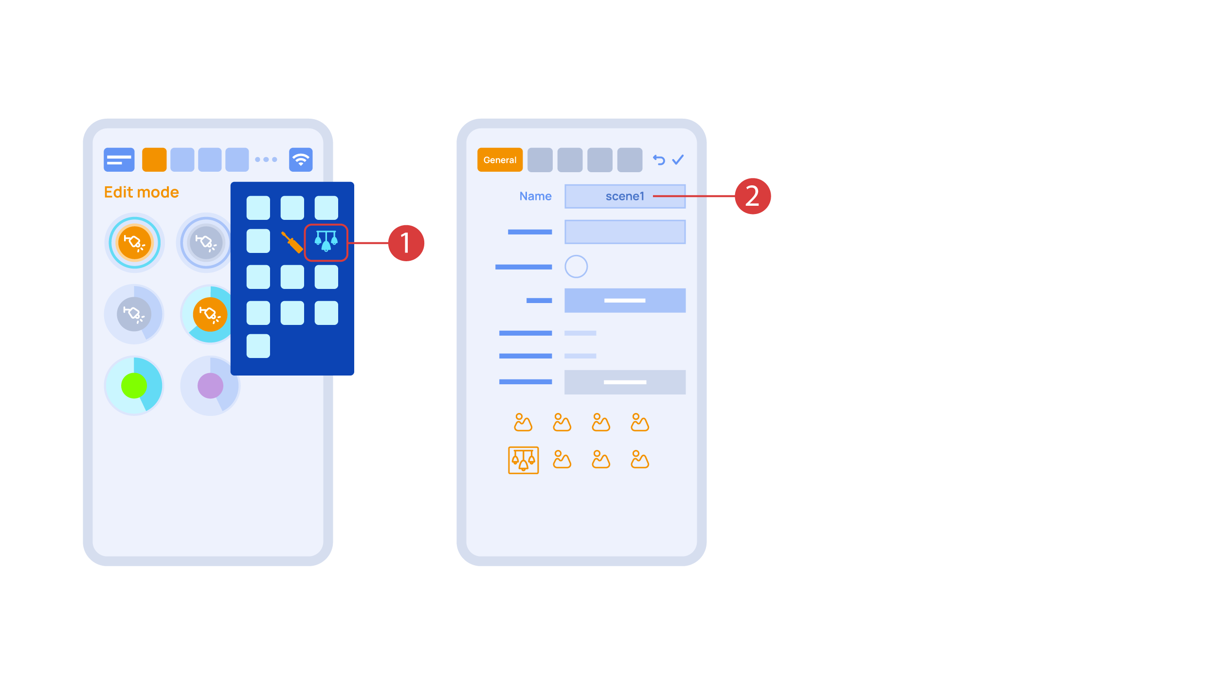
Let’s create a light scheme. For this we need to select the appropriate item in the additional menu ①. Give the light scheme a name ②.
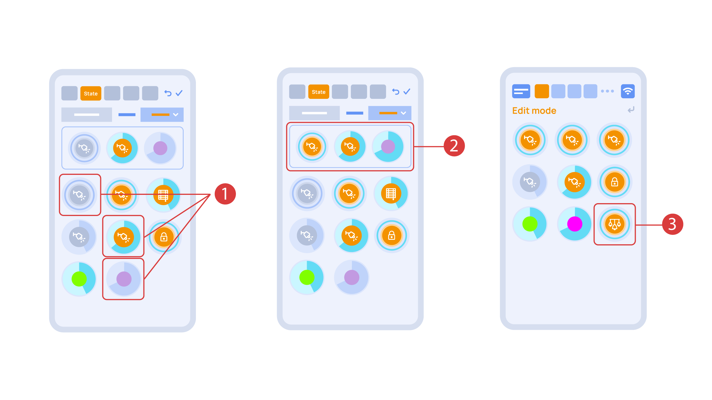
In the ‘State’ tab, use a long press to add the lights we want to use into the light scene ① and set up their state ②. ‘Auto’, ‘Schedule’, ‘Switch’ tabs are the same for all the executors.
Save the changes and we are able to use the newly-created light scheme ③ immediately.
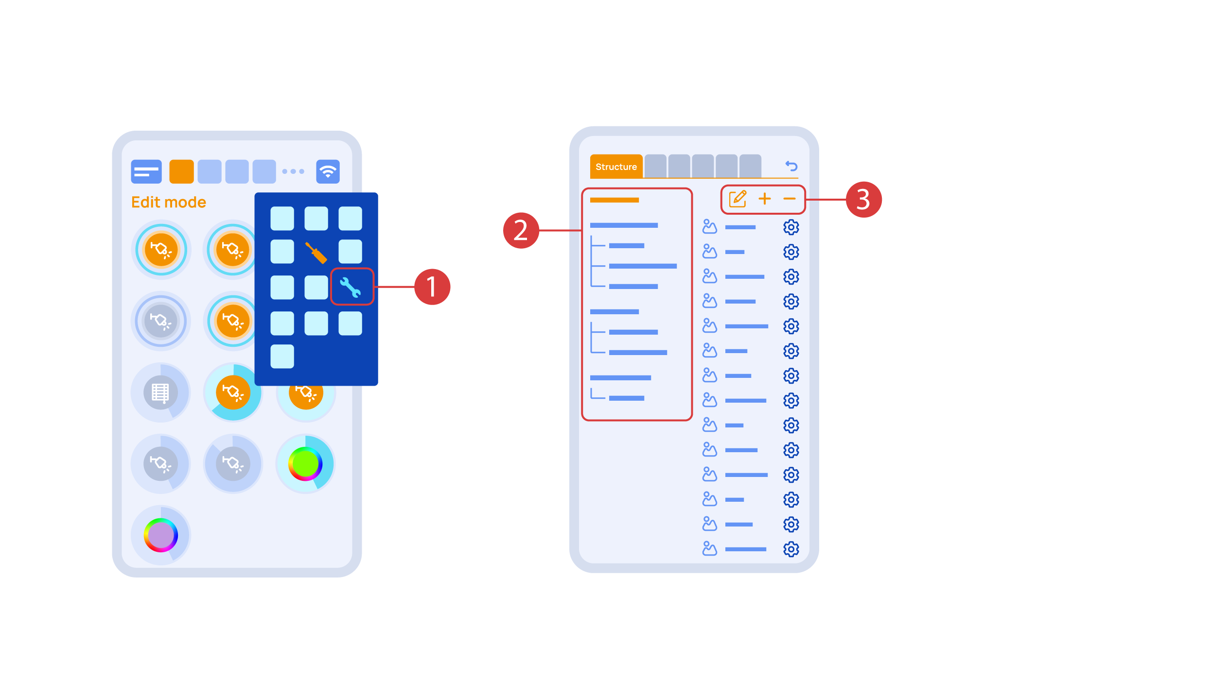
While you are in the Edit Mode, there is a ‘Setup’ ① icon in the additional menu.
Here in the ‘Structure’② tab we can see all the areas.
We can create new ones ④, rename them and move the elements around.
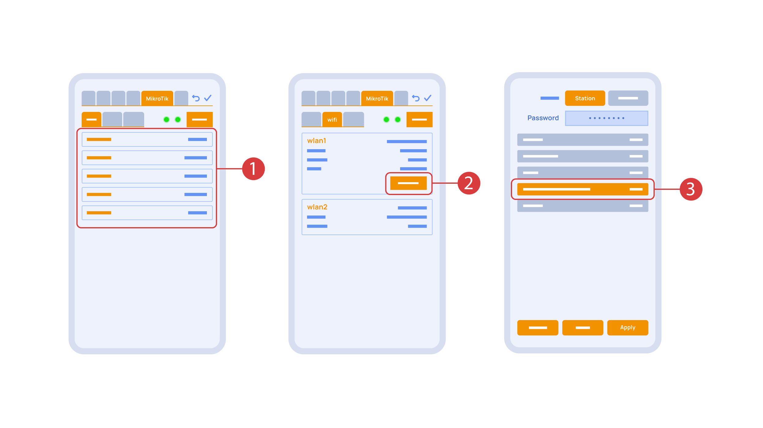
In the ‘Mikrotik’ tab ① you can see the current parameters of your router, which you can also connect to your local Wi-Fi network.
In order to do this, enter the Wi-Fi sub-menu, click the wlan1 interface configuration ②, after which choose the ‘station’ mode, choose a Wi-Fi network out of the list ③ of available ones and enter the connection password.
In the ‘Backups’ tab ① you can see the list of saved configurations, which can be restored if necessary.

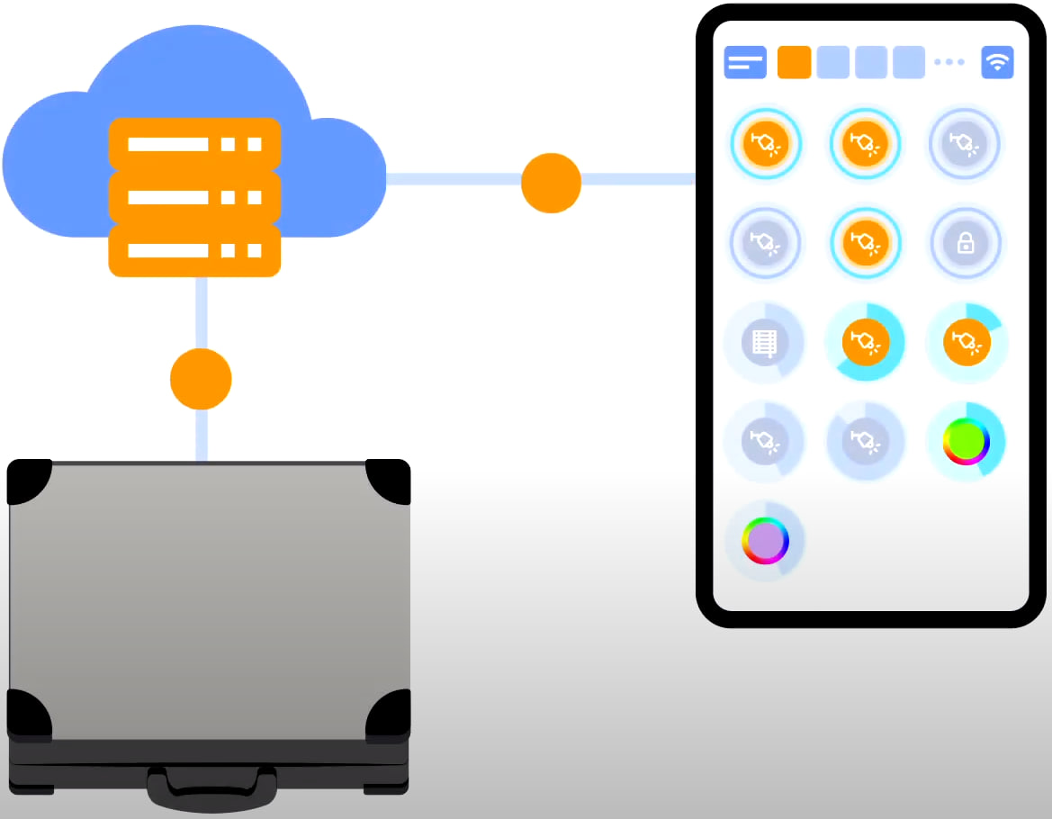
For cloud access to the device, you do not need any extra settings. The app detects the absence of the system in your local network and automatically establishes the connection via the cloud.
We thank you for watching this tutorial! If you have questions or need extra help, please do not hesitate to refer to our technical support team. See you in the next episodes!