Difference between revisions of "Metaforsa2 MF-14/pt"
(Created page with "A visão geral do módulo é mostrada na '''fig. 1'''") Tags: Mobile web edit Mobile edit |
(Created page with "700px|frameless|left|Fig. 1 Module general view <br> {| class="wikitable" style="clear:left;" |- |1 || — conector para aplicação de carga |- |2 || —...") Tags: Mobile web edit Mobile edit |
||
| Line 240: | Line 240: | ||
{| class="wikitable" style="clear:left;" | {| class="wikitable" style="clear:left;" | ||
|- | |- | ||
| − | |1 || — | + | |1 || — conector para aplicação de carga |
|- | |- | ||
| − | |2 || — | + | |2 || — conector para aplicação de lâmpadas dimmer |
|- | |- | ||
| − | |3 || | + | |3 || - conector de força |
|- | |- | ||
| − | |4 || — Ethernet | + | |4 || — Conector de rede Ethernet |
|- | |- | ||
| − | |5-6 || — | + | |5-6 || — conectores para sensores digitais e botões/unidades de comutação |
|- | |- | ||
| − | |7 || — OneWire | + | |7 || — Conector de interface OneWire (para sensores digitais) |
|- | |- | ||
| − | |8 || — | + | |8 || — conector para módulo de expansão. |
|} | |} | ||
Revision as of 14:50, 4 March 2024
| MF-14 | |||||||||||||
|---|---|---|---|---|---|---|---|---|---|---|---|---|---|
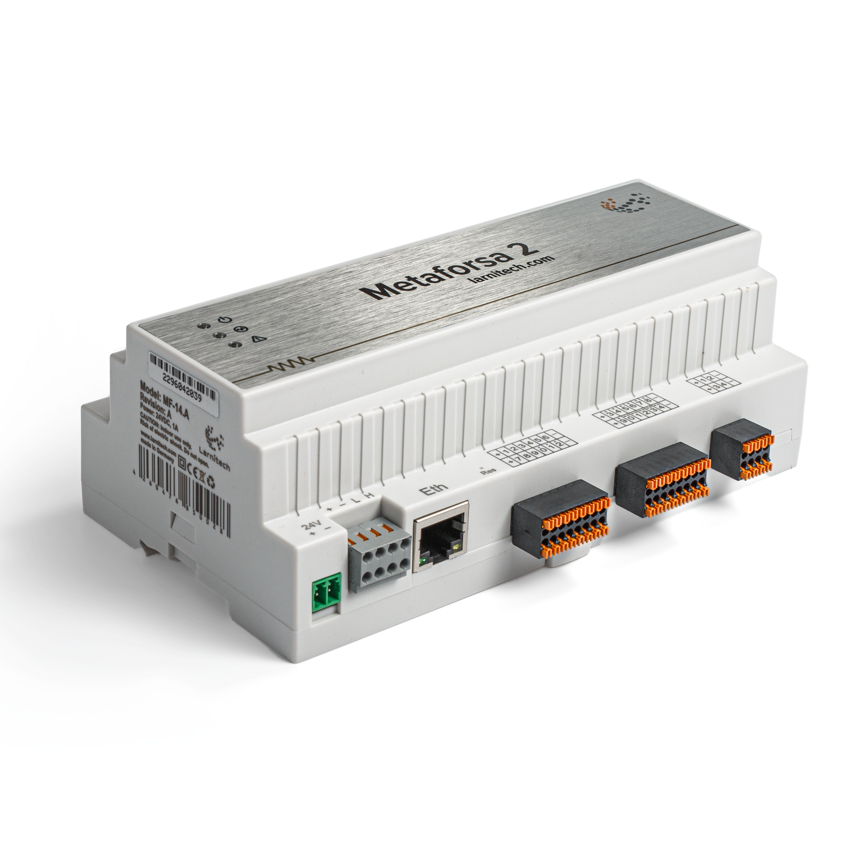 | |||||||||||||
| |||||||||||||
| |||||||||||||
| |||||||||||||
Introdução
O Manual de Instalação METAFORSA SMART HOUSE descreve o procedimento para sua instalação, montagem, operação e configuração. Ao trabalhar com o sistema, você deve cumprir rigorosamente todos os requisitos estabelecidos neste manual. O não cumprimento pode resultar em danos ao dispositivo, sua falha, choque elétrico, incêndio e outras consequências. O fabricante reserva-se o direito de fazer alterações neste manual sem aviso prévio. Este manual é parte integrante do sistema e deve permanecer com o cliente final.
Recursos
- Suporte para 10 saídas universais:
- Luzes
- Válvulas de aquecimento NC/NO
- Persianas
- Portões de 1 ou 2 pólos
- Válvulas de 1 ou 2 pólos
- Bloqueios NC/NO
- Unidades ventiloconvectoras
- 4 saídas de escurecimento
- 24 entradas discretas que suportam:
- Botões
- Comuta
- interruptores reed
- sensores de vazamento
- detectores de movimento
- 4 entradas digitais para até 8 sensores de temperatura
- Porta de extensão
- Relés com contatos AgSnO2 classificados para corrente de partida de 80A 20ms
- Conexão em nuvem e controle de todos os sistemas domésticos
- Controle de voz (Siri, Alexa, Google Home)
- O mecanismo de plug-ins permite expandir as possibilidades do sistema (por exemplo, integração com Satel, Philips Hue, luzes IKEA)
- Segurança contra invasões não autorizadas garantida com criptografia RSA/AES256
- Notificações push do sistema do seu telefone (também é possível receber através dos mensageiros Telegram e Viber)
- Histórico (os dados do medidor são armazenados por 1 ano)
- Plug and play (possibilidade de extensão rápida e fácil do sistema)
- Atualizações regulares do sistema
- Grande banco de dados de scripts constantemente atualizado para atender a todas as suas necessidades
- Backups diários automáticos via nuvem com possibilidade de restaurar a configuração inicial
- API aberta (que permite integrar Larnitech em outros sistemas)
- Interface Web LT SETUP interativa e fácil de usar disponível para configuração avançada
- Plug and play
- É um kit de sistema Smart Home totalmente pronto para instalar
Requisitos de segurança
Para evitar o risco de incêndio, choque elétrico, danos ao sistema e/ou ferimentos pessoais, a instalação e montagem do sistema devem ser realizadas de acordo com as instruções listadas abaixo:
- todos os trabalhos de ligação devem ser realizados sem energia;
- utilizar ferramentas adequadas e proteção individual contra choques elétricos;
- não utilize cabos, fios e conectores danificados;
- evite dobrar cabos e fios;
- não aperte ou dobre os cabos e fios aplicando força excessiva. Caso contrário, os condutores internos do cabo e dos fios poderão ficar descascados ou quebrados;
- não utilize tomada com mau contato para conectar;
- não exceda o limite dos parâmetros de carga especificados neste manual;
- a seção do fio dos condutores de alimentação está sujeita às especificações de limite de densidade de corrente, tipo de isolamento e material do fio. A seção leve pode resultar em superaquecimento do cabo e incêndio.
Ao trabalhar com o sistema após alimentação de tensão NUNCA:
- fazer conexão/desconexão de conectores;
- módulos e sensores abertos.
Configuração e finalidade do sistema
Objetivo do sistema
METAFORSA SMART HOUSE é uma solução pronta para automação de instalações residenciais e comerciais, complexos hoteleiros que inclui as características mais desejadas da Smart House.
O dispositivo possui 10 canais de controle, 4 canais de dimerização, 24 canais de sensores de entrada e uma porta de conexão de sensores digitais.
| As saídas universais podem ser usadas para controlar: | As entradas universais permitem conectar: |
|---|---|
| Iluminação | Botões/unidades de comutação |
| Conectores de soquete | Interruptores reed magnéticos |
| Aquecimento por piso radiante | Sensores de movimento |
| Atuadores de cortina/portão | Sensores de vazamento |
| Válvulas de abastecimento/aquecimento de água |
Porta de conexão de sensores digitais
A porta de conexão de sensores digitais permite conectar uma variedade de sensores digitais, como sensores de temperatura, luz ambiente, umidade e outros.
Porta de expansão
A porta de expansão permite atualizar o sistema conectando equipamentos auxiliares, como módulo de controle de iluminação LED, dimmer, dispositivos de medição e outros elementos.
O pacote, totalmente pronto para instalação, inclui hardware e software básicos.
Conteúdo do pacote
O pacote vem de fábrica com:
| Mainframe METAFORSA MF-14.А | 1 unidade |
| Fonte de alimentação MEANWELL DR-15-12 | 1 pc |
| Sensor de movimento CW-MSD | 3 pecas |
| Sensor de vazamento FW-WL.A | 2 peças |
| Elemento sensível à temperatura FW-TS.A | 4 PCS |
| Interruptor magnético de lâminas (sensor de posição de janela/porta) | 4 PCS |
| Filtro de ruído do cabo Ethernet | 1 pc |
| Cabo de alimentação | 1 pc |
Especificações técnicas básicas do Sistema
As especificações e características básicas do módulo METAFORSA MF-14.A são mostradas na tabela 1
| Especificação | Significado |
|---|---|
| Portas de saída | |
| Número de canais comutados | 10 |
| Número de grupos comutados | 10 |
| Número de canais de regulação de intensidade | 4 |
| Tensão de comutação | 0-250 V CA/CC |
| Carga máxima (um canal) | 16A |
| Carga máxima (dispositivo) | 160A |
| Carga máxima por canal de dimerização | 0,5A (110W a 220V) |
| Tipo de dimmer | MOSFET |
| Tipo de carga de dimmer | R,C |
| Tipo de escurecimento | borda de fuga |
| Tipo de conexão do cabo de alimentação | conector |
| Seção permitida do cabo de alimentação para conectar no soquete: cabo de condutor único cabo de condutores múltiplos cabo de condutores múltiplos com ponta |
0,5 … 4mm2 0,5 … 4mm2 0,5…2,5mm2 |
| Portas de entrada | |
| Número de entradas discretas | 24 |
| Número de entradas digitais | 4 |
| Classe máxima de corrente nos conectores de tensão de corrente contínua | 50mA |
| Outro | |
| Temperatura ambiente de funcionamento | 0 … +45°С |
| Temperatura de armazenamento/transporte | -20… +60°С |
| Umidade admissível | 0… 95% (sem condensação) |
| Fonte de alimentação | 12 … 27,5 V CC 24 V, 0,75 A Recomendado |
| Procura máxima | 0,5А |
| Interfaces disponíveis | Ethernet, CAN, OneWire |
| Tipo de barramento | CAN (4 fios) |
| CAN (4 fios) | 800 m* (par trançado 5 gato) |
| Tipo de fio CAN | FTP Cat 5E |
| Tipo de conexão CAN | conector |
| Comprimento máximo da linha digital | 30 metros |
| Tipo fio de linha digital | UTP/FTP Cat5E |
| Comprimento máximo da LAN | 100 metros |
| Tipo de fio LAN | UTP/FTP Cat5E |
| Tipo de conexão LAN | Conector RJ-45 |
| Especificações dimensionais | 9U, 156x110x58mm |
| Material da casca | Plástico ABS |
| Invólucro | IP40 |
| Tipo de instalação do equipamento | Trilho DIN (EN 60715) |
| Peso | 400g |
* – a instalação de unidades de fonte de alimentação adicionais é necessária para linhas longas; o comprimento máximo da linha pode ser reduzido por vários fatores de interferência
Estrutura geral do Sistema
A visão geral do módulo é mostrada na fig. 1
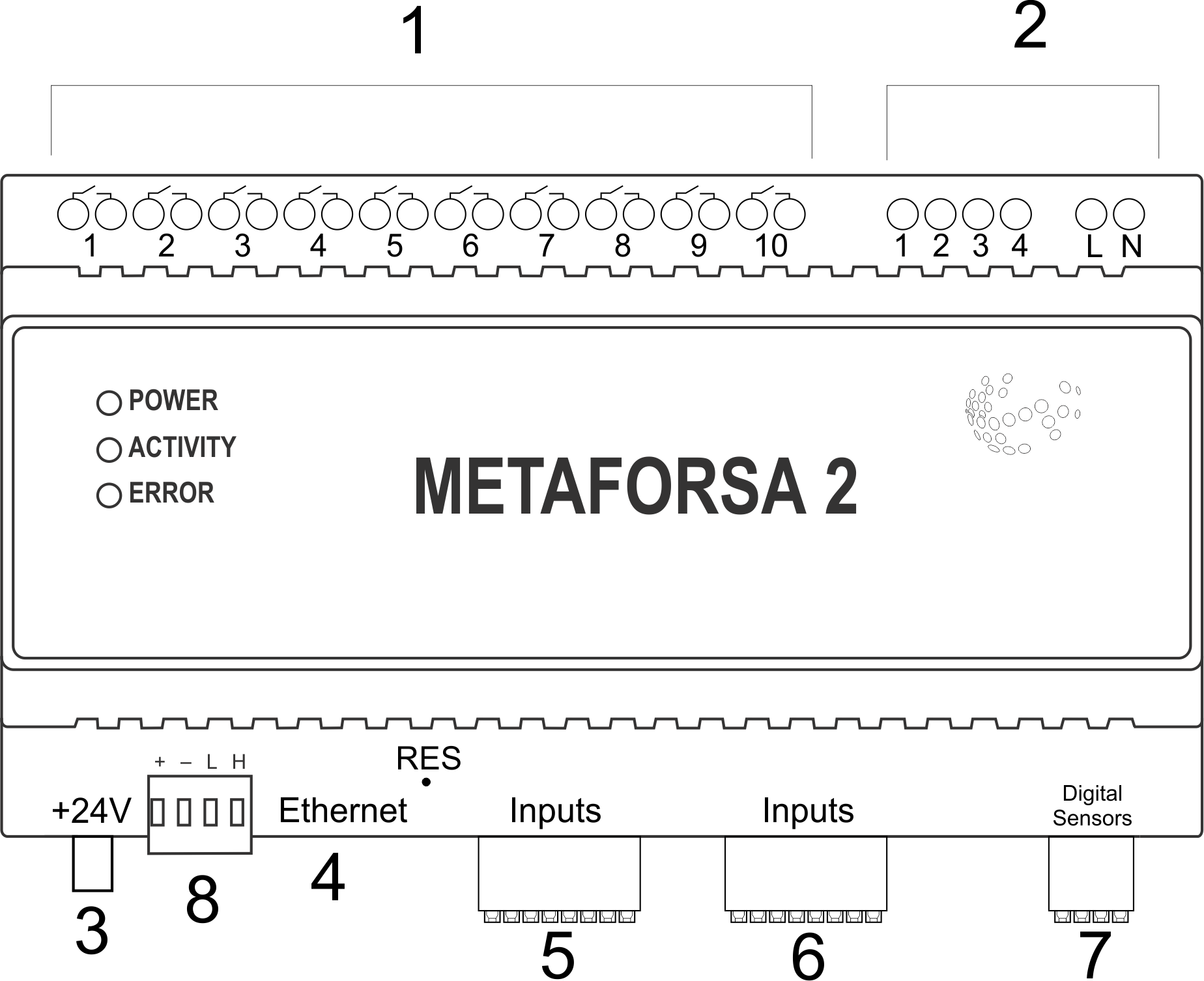
| 1 | — conector para aplicação de carga |
| 2 | — conector para aplicação de lâmpadas dimmer |
| 3 | - conector de força |
| 4 | — Conector de rede Ethernet |
| 5-6 | — conectores para sensores digitais e botões/unidades de comutação |
| 7 | — Conector de interface OneWire (para sensores digitais) |
| 8 | — conector para módulo de expansão. |
Overview of the METAFORSA device external connectors:
At the top of the casing (fig. 1) there is:
- connector (1) — Devices connection;
- connector (2) — Dimming lamps connection;
At the bottom of the casing (fig. 1) there is:
- connector (3) — module power supply connection;
- connector (4) — Ethernet network connection;
- connectors (5-6) — four six-point connectors for digital sensors connection – motion, leakage, reed switch sensors, and *button/switching unit sensors;
- connector (7) — OneWire digital sensors bus connection;
- connector (8) — expansion module connection.
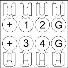
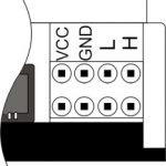
The physical configuration and contact point assignment of each connector are shown in table 2.
| Connector | Contact | Assignment |
|---|---|---|
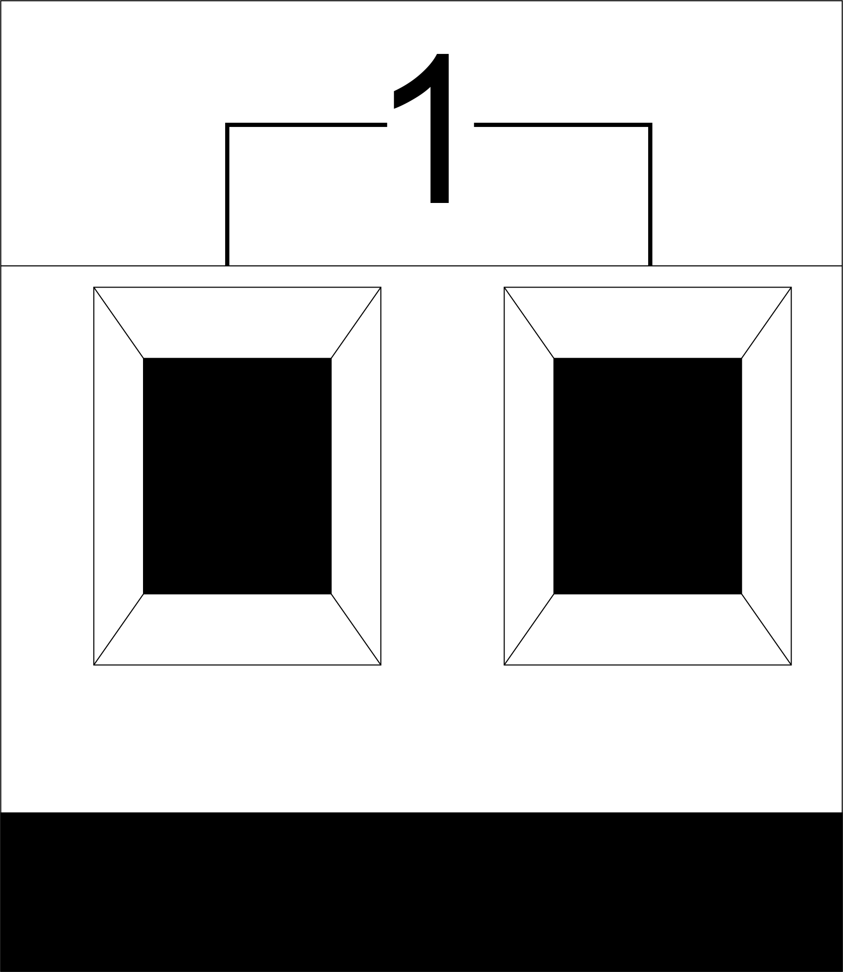 |
1-10 | Load application (light lamps, thermal actuators, etc.) |
| D1-4, L, N | Load application (dimming lamps) | |
| Device status indicators | The module status indicators are described in table 3 | |
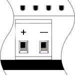 |
+24V GND |
+24V — module power supply by an external 24 V power supply GND — common |
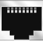 |
RJ45 | Connector for LAN connectivity |
| In1-12, In13-24 GND | Controlling devices connection (buttons, magnetic reed switches, motion or leakage sensors): +12V — sensor power output +12 V In1 … In24 — logic inputs (0-12 V) GND — common | |
 |
OneWire | Digital sensors connection (temperature) VCC — sensors power supply output +5V OW1-OW4 — OneWire data buses GND — common |
 |
VCC GND L H |
External modules connection for CAN-bus VСС — 24V output for external devices power supply GND — common L — CAN-L data bus H — CAN-H data bus |
| Indicator | Status | Description |
|---|---|---|
| Power | Power | |
| Power not available | ||
| Activity | Data communication | |
| Data communication not available | ||
| Error | No errors | |
| Communication error | ||
| Module overheat | ||
| Dimmer outputs module overload | ||
| Absence of power on dimmers, if in configuration |
System installation and assembly
Before connecting the system, you must:
- site the sensor and actuators (if not pre-installed), set the sensors and actuators;
- site the module and power supply.
Note: The module must be installed near the power supply voltage source.
- The power of circuit breaker assembly must comply with the load capacity;
- Nothing else than the phase conductors can be connected to the module, the neutral wire is connected separately.
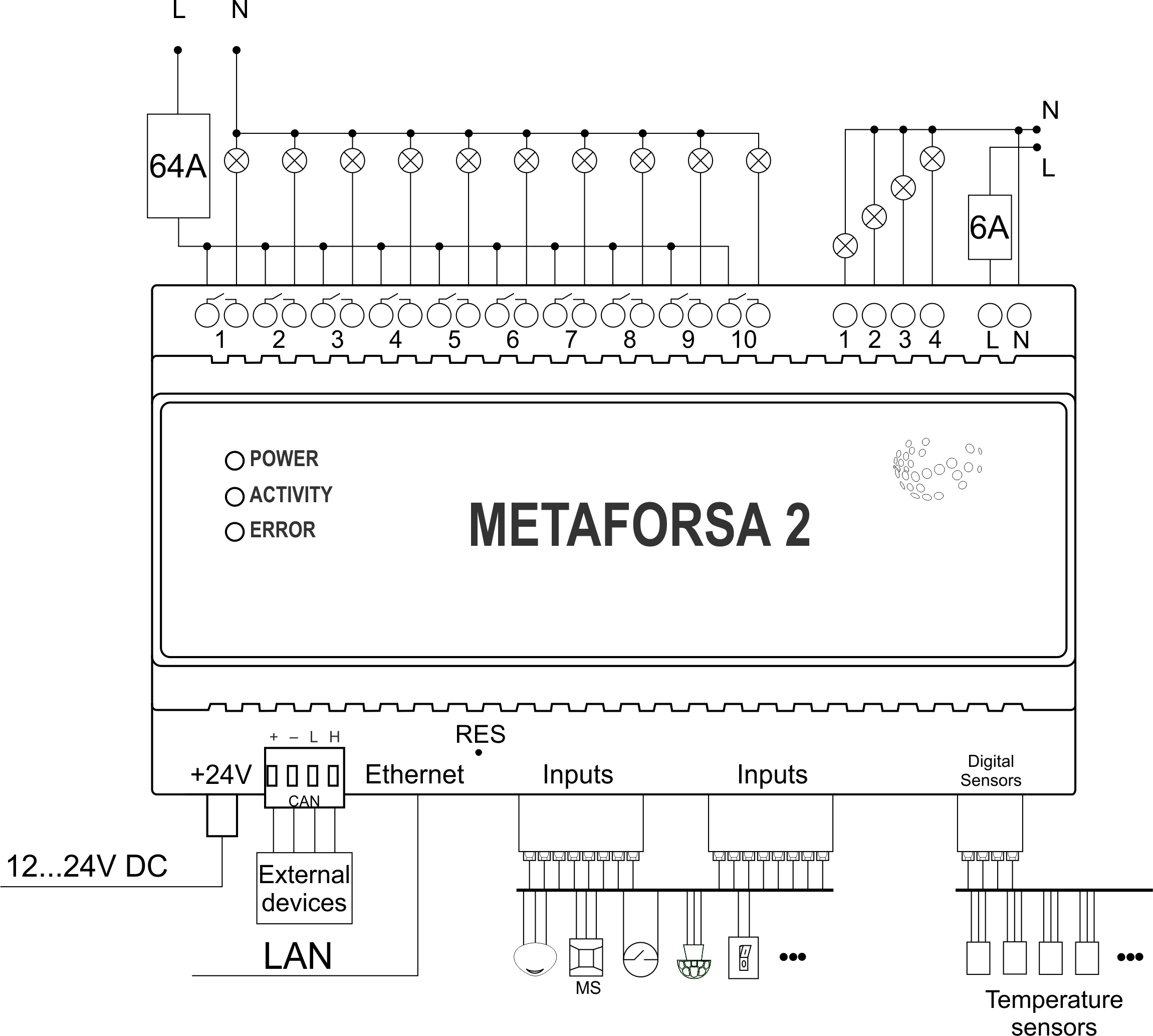
Typical diagram of METAFORSA MF-14.A module connection is shown in fig. 3.
Connection of the actuators
Connection of the lights/electric contactor/heating thermal actuator
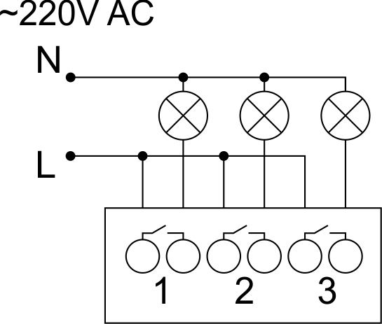 Fig. 4 |
Such actuators as light, electric contactor, heating thermal actuator should be switched on any of the outputs 1 – 10, the neutral wire and the ground wire should be connected directly to the switchboard. The example of connection is shown in Fig.4. |
Connection of high load device
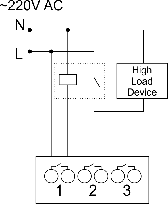 |
Recomended contactors:
|
Connection of single-pole water/gas supply valve
| Caution: Before applying power to the load, make sure that the output configuration of METAFORSA module is correct. The incorrect configuration or incorrect connection can cause the module failure and/or failure of the equipment connected to it, and even a fire. | |
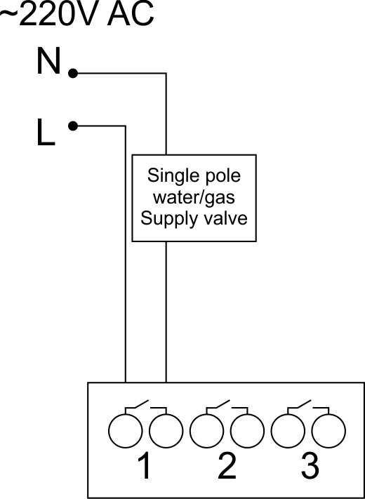 Fig. 5 |
The single pole water/gas supply valve is connected to any of the outputs of 1 – 10, the (neutral wire and the ground wire are connected directly to the switchboard. The example of connection is shown in Fig.5. |
Connection of double-pole water/gas supply valve
| Caution: Before applying power to the valve, it is necessary to ensure the output configuration of METAFORSA module is correct. The incorrect configuration can cause the voltage application simultaneously to both channels of the valve, which may result in the module failure and/or failure of the equipment connected to it, and even a fire. | |
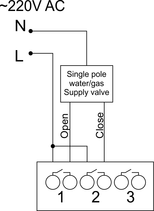 Fig. 6 |
Two adjacent contact points (for example, 3, 4) are used to connect the double-pole water/gas supply valve; in these conditions the neutral wire and the ground wire are connected directly to the switchboard. The example of connection is shown in Fig.6. |
Connection of single-pole gate actuator
| Caution: Before applying power to the module, you should properly configure access to the application. The contacts incorrectly configured can result in the module failure and/or failure of the equipment connected to it, and even a fire.
| |
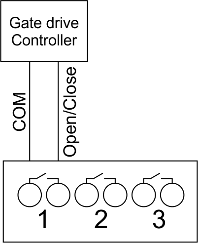 Fig. 7 |
Any contact point (for example, 3) is used to connect the single-pole gate drive controllers. The example of connection is shown in Fig.7. |
Connection of double-pole gate actuator
| Caution: Before applying power to the module, you must properly configure the outputs in the application. The contacts configured incorrectly can lead to simultaneous power supply to both channels, resulting in the module failure and/or failure of the equipment connected to it, and even a fire.
| |
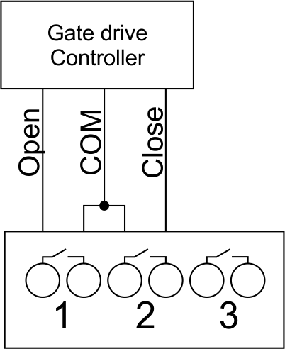 Fig. 8 |
Two adjacent contact points (for example, 3, 4) should be used to connect the double-pole gate drive controller. The example of connection is shown in Fig.8. |
Connection of curtain/jalousie/shutter actuator with 220V force control
| Caution: Before applying power to the module, you must properly configure the outputs in the application. The contacts configured incorrectly can lead to simultaneous power supply to both channels, resulting in the module failure and/or failure of the equipment connected to it, and even a fire.
| |
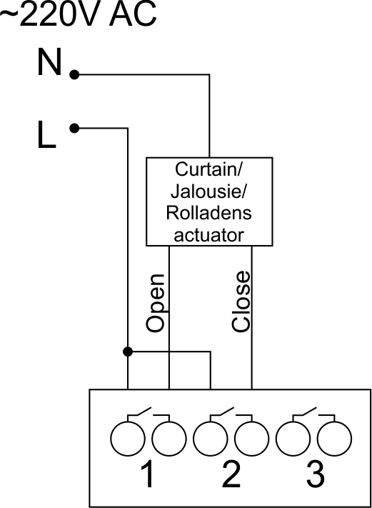 Fig. 9 |
Two adjacent contact points (for example, 3, 4) should be used to connect the curtain/jalousie/rolladens actuator, in these conditions the neutral wire and the ground wire are connected directly to the switchboard. The example of connection is shown in Fig.9. |
Connection of curtain/jalousie/shutter actuator with low-voltage control
| Caution: Before applying power to the module, you must properly configure the outputs in the application. The contacts configured incorrectly can lead to simultaneous power supply to both channels, resulting in the module failure and/or failure of the equipment connected to it, and even a fire.
| |
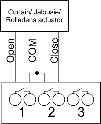 Fig. 10 |
Two adjacent contact points (for example, 3, 4) should be used to connect the curtain/jalousie/rolladens actuator with low-voltage control. The example of connection is shown in Fig.10. |
Connection of sensing elements/switches/buttons
Connection of motion sensors
The motion sensors should be connected to any free input in1-in24; in these conditions their power is connected to the contact points of +12V and GND of the relevant group. The example of connection is shown in Fig.11.
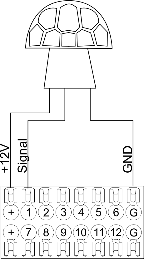
Fig. 11
Connection of FW-WL.A leakage sensors
FW-WL.A leakage sensors are connected to any free input in1 – in24, in these conditions the power should be connected to +12V and GND points of the relevant group. The example of connection is shown in fig. 12.
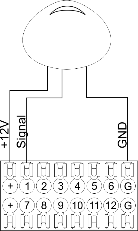 Fig12 |
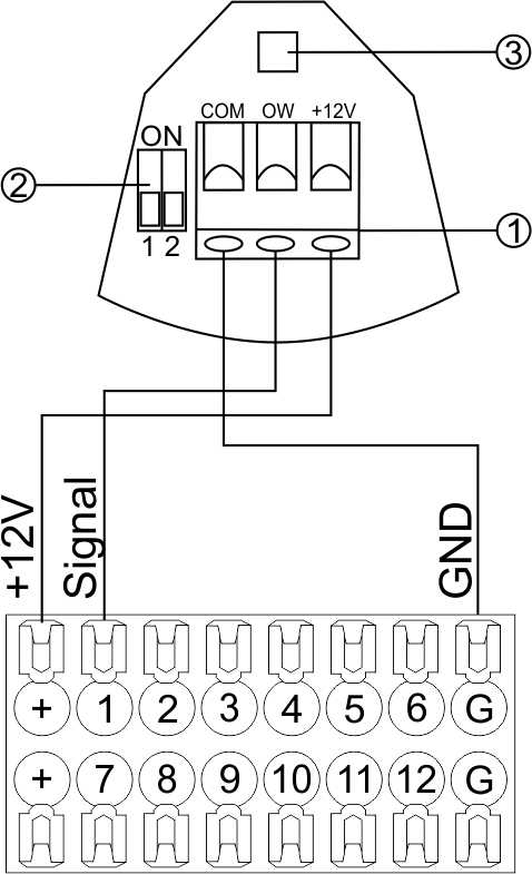 Fig13 |
Configuration and connection of the FW-WL.A sensor 1. Terminals:
- +12V — sensor power is connected to the contact point of METAFORSA “+12V”;
- OW — sensor pickup signal;
- GND — common, connected to GND contact of METAFORSA.
2. Sensor preset switch (optionally):
- 1 — sensor sensitivity (ON – high, OFF – low);
- 2 — indicator colour setting (ON – blue, OFF – green).
3. LED status indicator.
Connection of buttons/switches/magnetic reed switches
Buttons and reed switches are connected to any free input in1-in24, while their second contact point is connected to GND point of the relevant METAFORSA module group, + 12V power outputs – not in use. The example of connection is shown in Fig. 14-15.
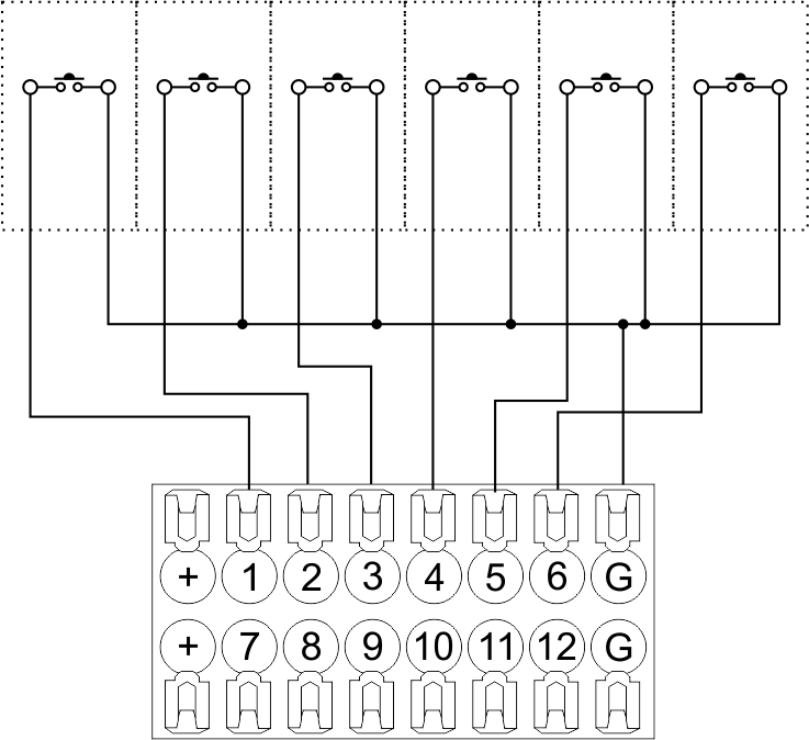 Fig14 connection of buttons/switching units |
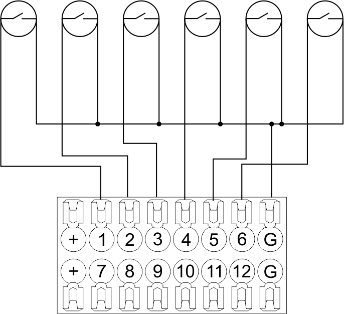 Fig15 connection of the magnetic reed switches (window/door position sensors) |
Connection of digital sensors
The OW adapter (Fig. 16a) is supplied along with METAFORSA module with the possibility to connect up to 8 digital sensors to it. In these conditions, several devices can be connected to one channel (Fig. 16b). The connected sensors are detected automatically and do not require any original setting.
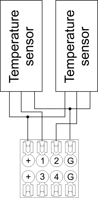 Fig16 a |
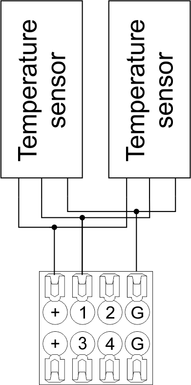 Fig16 b |
Configuration and connection of the OW adapter
Connection of auxiliary equipment.
Expansion modules include Larnitech equipment connected through the CAN-bus. Such equipment includes: dimmers, RGB-backlit control modules, multimode sensors, etc. The equipment connected to the expansion port is defined automatically and does not require any preset tuning. Connector contact pin assignment is defined in Table 4. The example of connection is shown in Fig. 17.

|
| Caution! The 120 ohm terminating resistors should be installed at the end connectors between L and H contact points of CAN-bus. Ensure the connection is correct. The incorrect connection may cause sensor and/or module malfunction. |
Module installation and connection procedure
- Install the module in the switchboard on the DIN-rail and fix it with the special latch on the module base.
- Fasten the supply unit on the left side of the module.
- Connect the connector (4) having the noise filter pre-installed which is supplied complete with the module.
- Connect the connectors (5), (6).
- Connect the connectors (1), (2).
- Connect the connector (3).
- Apply power to the supply unit of METAFORSA module.
- Wait until the module is loaded, then configure it in accordance with the System Setup Instructions.
- Apply power to the connectors (1), (2).
- Check all equipment for proper operation.
METAFORSA module shut-off and deinstallation procedure
- De-energize the module by disconnecting the circuit breaker assembly of the load power supply and METAFORSA module supply unit. Verify the voltage is absent on the terminals (1), (2) of the connector wires and on the input terminals of the supply unit.
- Disconnect the load power supply connectors (1), (2).
- Disconnect the connector (3).
- Disconnect the connectors (4)-(6).
- Remove the module from the DIN-rail, releasing the latch at the bottom of the module base.
Hardware setup
To configure and control METAFORSA SMART HOUSE, you must install Larnitech software on your smartphone or tablet, which is available in App Store and Play Market. After installation, follow the System Setup Instructions.
Fault diagnostics and handling
The following are some possible faults and ways of fault handling. If you have any difficulty, or face the fault undeclared here, please contact the Technical Support: [1] or [support@larnitech.com]. There are also some tips in the FAQ section at our website [2].
The actuators do not operate:
- ensure the outputs are properly configured in the application (see System Setup Instructions);
- check the connection is correct in accordance with table 2 and paragraph 3.6;
- ensure the power is supplied to the input power contact , i.e. all circuit breaker assembly are ON.
- verify the operability of the connected equipment.
The module is off, indication absent:
- check the connection to 24V supply unit as shown in table 2 (contacts pin assignment);
- check the connection of the supply unit to 220V power mains, the indicator should be ON.
Network connection fault:
- ensure the Ethernet cable is properly wired and connected to the connector;
- ensure the LED status indicators are ON on the Ethernet connector;
- check the LAN configuration is correct, Ethernet cable loops are absent;
- METAFORSA module and the device you are connecting from are in the same network.
hold integer 0-10000 1-10 by default hold is the same as runtime hold is the bridging time in miliseconds, is used for gate and jalousie, lock; Example: hold=3500
The sensors do not operate:
- ensure the inputs are properly configured in the application (System Setup Instructions);
- check the connection is correct in accordance with table 2 and paragraph 3.7;
- ensure the METAFORSA module is ON: circuit breaker assembly is closed, indication on the supply unit is ON, the module indication corresponds to the operating status – table 3;
- check the power supply availability on the sensors;
- check the integrity of lines laid to the sensors.
The auxiliary equipment does not operate:
- check the connection is correct in accordance with table 2 and paragraph 3.8-9;
- ensure the METAFORSA module is ON: circuit breaker assembly is closed, indication on the supply unit is ON, the module indication corresponds to the operating status – table 3;
- check the integrity of the CAN lines, voltage supply on the modules.
HW Settings
| Name | Type, range | SUBID | Default | Description |
|---|---|---|---|---|
| runtime | integer 0-100 | 1-10 | 15 | runtime is the open/close time in seconds, is used for jalousie, gate, valve(2 pole);
|
| runtimeopen | integer 0-60000 | Blinds subId | Runtimeopen is the open time in milliseconds, is used for blinds; Example: runtimeopen=15000 | |
| runtimeclose | integer 0-60000 | Blinds subId | Runtimeclose is the close time in milliseconds, is used for blinds; Example: runtimeclose=15000 | |
| hold | integer 0-10000 | 1-10 | 500 | hold is the bridging time in milliseconds, is used for gate and jalousie (by default hold is the same as runtime for jalousie and gate), lock; Example: hold=3500 |
| def | string 'ON' | 1-10 | 'OFF' | def is the element status is set after restart, is used for lamp, heating, valve(1 pole); Example: def='ON' |
| stop | Char ‘R’ | 1-7 | – | (for 2-pole gate and blinds) If it is declared then by Stop command during the motion, the same impulse appears as it was at the beginning of the motion. Pole, an which the stop-impules is formed, is defined by the parameter Stop value. If it is ‘r’ or ‘R’ then stop-impulse is produced on the opposite to the start-impulse pole. If any other value is delcared (e.g., ‘d’ ) then the stop-impulse is on the same pole. If a Runtime passed after the beginning of the motion then the stop-impulse is not formed. Example: stop=’r’ |
| out | char[10] | 98 | 'LLLLHHHHP-' | Each char is responsible for the type of a particular channel
Example: out='LLB-G-V-W-' |
| dm | char[4] | 98 | ‘LLLL’ | Each char is responsible for the type of a particular channel
Example: dm=’skl-‘ |
| def | integer 0-250 | 11-14 | 100 | The default brightness level in case of a power reset (1..250). Example: def=250 |
| min | integer 0-100 | 11-14 | 0 | Minimum dimming level, example: min=10 |
| max | integer 0-100 | 11-14 | 100 | Maximum dimming level, example max=95 |
| start | integer 0-100 | 11-14 | 0 | The Start function is used for lamps that lack the minimal voltage to get turned on. If the set value is lower than the start value, the lamp is turned on at the start value and them the light is dimmed down to the set level. Example: start=60 |
| force | integer 0-100 | 11-14 | 10 | Time duration of the starting value (measured in milliseconds). Example: force=20 |
| runtime | integer 0-60000 | 11-14 | 1000 | Runtime is the speed of changing the brightness from ‘min’ to ‘max’ (measured in milliseconds). Example: runtime=1000 |
| offset | integer (+/- 0…39) | 39-46 | '0' | sensor values offset; For example, offset is -3.8 :
Example: hw="offset='-3.8'" |
| in | char[24] | 98 | 'BBBBBBBBBBBBMMMLLLKKKKKK' | Each char is responsible for the type of a particular channel
Example: in='MMMMMMMMMMMMLLLLLLLLLLLL' 12 motion sensors and 12 leak-sensors; in='BBBBBBBBSSSSSSBBBBSSSSSS' 12 buttons; 12 switches. |
 1<item addr="339:1" auto-period="600" cfgid="40" hw="def='ON'" name="Lamp" type="lamp" uniq_id="3779">
 2<item addr="339:2" cfgid="40" hw="def='ON'" name="Radiator" type="valve-heating" uniq_id="3780">
 3    <automation name="Eco" temperature-level="16" uniq_id="3781"/>
 4    <automation name="Comfort" temperature-level="22" uniq_id="3782"/>
 5    <automation name="Hot" temperature-level="25" uniq_id="3783"/>
 6</item>
 7<item addr="339:3" cfgid="40" hw="runtime=9" name="Jalousie" sub-type="120" type="jalousie" uniq_id="32"/>
 8<item addr="339:5" cfgid="40" hw="runtime=13" name="Gate" sub-type="120" type="gate" uniq_id="3784"/>
 9<item addr="339:7" cfgid="40" hw="hold=4600" name="Gate" sub-type="120" type="gate" uniq_id="3785"/>
10<item addr="339:8" cfgid="40" hw="runtime=10" name="Valve" type="valve" uniq_id="3786"/>
11<item addr="339:11" cfgid="40" name="Motion" type="motion-sensor" uniq_id="17"/>
12<item addr="339:12" cfgid="40" name="Motion" type="motion-sensor" uniq_id="18"/>
13<item addr="339:13" cfgid="40" name="Motion" type="motion-sensor" uniq_id="19"/>
14<item addr="339:16" cfgid="40" name="Leak" type="leak-sensor" uniq_id="21"/>
15<item addr="339:17" cfgid="40" name="Leak" type="leak-sensor" uniq_id="41"/>
16<item addr="339:19" cfgid="40" name="Switch" type="switch" uniq_id="22"/>
17<item addr="339:20" cfgid="40" name="Switch" type="switch" uniq_id="23"/>
18<item addr="339:21" cfgid="40" name="Switch" type="switch" uniq_id="24"/>
19<item addr="339:22" cfgid="40" name="Switch" type="switch" uniq_id="25"/>
20<item addr="339:23" cfgid="40" name="Door" type="door-sensor" uniq_id="26"/>
21<item addr="339:24" cfgid="40" name="Door" type="door-sensor" uniq_id="27"/>
22<item addr="339:25" cfgid="40" name="Door" type="door-sensor" uniq_id="28"/>
23<item addr="339:26" cfgid="40" name="Door" type="door-sensor" uniq_id="29"/>
24<item addr="339:30" cfgid="40" name="Temperature" type="temperature-sensor" uniq_id="3772"/>
25<item addr="339:31" cfgid="40" name="Temperature" type="temperature-sensor" uniq_id="3773"/>
26<item addr="339:32" cfgid="40" name="Temperature" type="temperature-sensor" uniq_id="3774"/>
27<item addr="339:33" cfgid="40" hw="offset='-10.8'" name="Temperature" type="temperature-sensor" uniq_id="3775"/>
28<item addr="339:34" cfgid="40" hw="offset='25.1'" name="Temperature" type="temperature-sensor" uniq_id="3776"/>
29<item addr="339:35" cfgid="40" name="Temperature" type="temperature-sensor" uniq_id="3777"/>
30<item addr="339:36" cfgid="40" name="Temperature" type="temperature-sensor" uniq_id="3778"/>
31<item addr="339:98" cfgid="40" hw="out='LHB-G-XV--' in='MMM--LL-BBBBKKKK'" name="Temperature" system="yes" type="temperature-sensor" uniq_id="30"/>