Difference between revisions of "Metaforsa2 MF-14/da"
(Created page with "{| class="wikitable" style="width:800px"; |- |colspan="2" style="background-color:#dededf" |'''Forsigtig: Før du tilslutter strøm til belastningen, skal du sikre dig, at out...") Tags: Mobile web edit Mobile edit |
(Created page with "====Tilslutning af dobbeltpolet vand/gas forsyningsventil====") Tags: Mobile web edit Mobile edit |
||
| Line 356: | Line 356: | ||
| − | ==== | + | ====Tilslutning af dobbeltpolet vand/gas forsyningsventil==== |
{| class="wikitable" style="width:800px"; | {| class="wikitable" style="width:800px"; | ||
Revision as of 08:50, 5 March 2024
| MF-14 | |||||||||||||
|---|---|---|---|---|---|---|---|---|---|---|---|---|---|
 | |||||||||||||
| |||||||||||||
| |||||||||||||
| |||||||||||||
Introduktion
METAFORSA SMART HOUSE Installationsmanual beskriver proceduren for installation, montering, betjening og indstilling. Mens du arbejder med systemet, skal du nøje overholde alle kravene i denne manual. Manglende overholdelse kan resultere i beskadigelse af enheden, dens fejl, elektrisk stød, brand og andet nedfald. Producenten forbeholder sig retten til at foretage ændringer i denne manual uden forudgående varsel. Denne manual er en integreret del af systemet og forbliver hos slutbrugeren.
Funktioner
- 10 universelle udgange understøtter:
- Lys
- NC/NO varmeventiler
- Persienner
- 1 eller 2-polede porte
- 1 eller 2-polede ventiler
- NC/NO låse
- Blæserkonvektorer
- 4 dæmpningsudgange
- 24 diskrete indgange, der understøtter:
- Knapper
- Switcher
- reed afbrydere
- lækagesensorer
- Bevægelsesdetektorer
- 4 digitale indgange til op til 8 temperatursensorer
- Forlængerport
- Relæer med AgSnO2-kontakter klassificeret til 80A 20ms startstrøm
- Skyforbindelse og kontrol af alle hussystemer
- Stemmestyring (Siri, Alexa, Google Home)
- Plugins-motor gør det muligt at udvide systemmulighederne (f.eks. integration med Satel, Philips Hue, IKEA lys)
- Sikkerhed mod uautoriseret indtrængen sikret med RSA/AES256-kryptering
- Push-meddelelser fra systemet på din telefon (også muligt at modtage via Telegram og Viber messengers)
- Historie (målerdata for 1 år er gemt)
- Plug and play (mulighed for hurtig og brugervenlig udvidelse af systemet)
- Regelmæssige systemopdateringer
- Stor konstant opdateret database med scripts for at opfylde alle dine behov
- Automatisk daglig backup via cloud med mulighed for at gendanne den oprindelige konfiguration
- Åben API (som gør det muligt at integrere Larnitech i andre systemer)
- Interaktiv og brugervenlig LT SETUP-webgrænseflade tilgængelig for avanceret konfiguration
- Tilslut og brug
- Det er et komplet klar til at installere Smart Home-systemsæt
Sikkerhedskrav
For at undgå risikoen for brand, elektrisk stød, beskadigelse af systemet og/eller personskade, skal installationen og monteringen af systemet udføres i overensstemmelse med instruktionerne nedenfor:
- alle tilslutningsarbejder skal udføres uden strøm;
- brug passende værktøj og personlig beskyttelse mod elektrisk stød;
- brug ikke beskadigede kabler, ledninger og stik;
- undgå foldning af kabler og ledninger;
- undgå at klemme eller knække kabler og ledninger ved at anvende for stor kraft. Ellers kan indvendige ledere af kablet og ledningerne blive strippet eller knækket;
- brug ikke stikkontakten med dårlige kontakter til at forbinde;
- overskrid ikke grænsen for belastningsparametre angivet i denne manual;
- forsyningsledernes ledningssektion er underlagt specifikationerne for strømtæthedsgrænse, isoleringstype og ledningsmateriale. Lyssektion kan resultere i kabeloverophedning og brand.
Når du arbejder med systemet efter spændingsforsyning ALDRIG:
- foretag tilslutning/frakobling af stik;
- åbne moduler og sensorer.
Systemkonfiguration og formål
Formål med systemet
METAFORSA SMART HOUSE er en færdiglavet løsning til automatisering af bolig- og erhvervslokaler, hotelkomplekser, som indeholder de mest eftertragtede funktioner i Smart House.
Enheden har 10 kontrolkanaler, 4 dæmpningskanaler, 24 indgående sensorkanaler og en digital sensorforbindelsesport.
| Universaludgange kan bruges til at styre: | Universalindgange giver dig mulighed for at tilslutte: |
|---|---|
| Belysning | Taster/koblingsenheder |
| Stikstik | Magnetiske reed-kontakter |
| Gulvvarme | Bevægelsessensorer |
| Gardin-/portaktuatorer | Lækagesensorer |
| Vandforsyning/varmeventiler |
Digitale sensorer tilslutningsport
Den digitale sensortilslutningsport giver dig mulighed for at tilslutte en række digitale sensorer, såsom temperatursensorer, omgivende lys, fugtighed og andet.
Udvidelsesport
Udvidelsesporten giver dig mulighed for at opgradere systemet ved at tilslutte ekstraudstyr, såsom styremodulet til LED-belysning, dæmpning, måleenheder og andre elementer.
Pakken, som er fuldstændig klar til at installere, inkluderer den grundlæggende hardware og software.
Pakkens indhold
Pakken leveres som standard med:
| Mainframe METAFORSA MF-14.А | 1 stk |
| Strømforsyningsenhed MEANWELL DR-15-12 | 1 stk |
| Bevægelsessensor CW-MSD | 3 stk |
| Lækagesensor FW-WL.A | 2 stk |
| Temperaturfølsomt element FW-TS.A | 4 stk |
| Magnetisk reed-kontakt (vindues-/dørpositionssensor) | 4 stk |
| Ethernet-kabel støjfilter | 1 stk |
| Strømforsyningsledning | 1 stk |
Grundlæggende tekniske specifikationer for systemet
De grundlæggende specifikationer og egenskaber for modulet METAFORSA MF-14.A er vist i tabel 1
| Specifikation | Betyder |
|---|---|
| Outputporte | |
| Antal skiftede kanaler | 10 |
| Antal skiftede grupper | 10 |
| Antal dæmpningskanaler | 4 |
| Kommuteringsspænding | 0-250 V AC/DC |
| Spidsbelastning (én kanal) | 16A |
| Spidsbelastning (enhed) | 160A |
| Maks. belastning pr. dæmpningskanal | 0,5A (110W ved 220V) |
| Lysdæmper type | MOSFET |
| Lysdæmper belastningstype | R,C |
| Lysdæmpningstype | bagkant |
| Strømforsyningskabeltilslutningstype | stik |
| Tilladt sektion af strømforsyningskablet til tilslutning i stikket: enkeltlederkabel flerlederkabel tilsluttet flerlederkabel |
0,5 … 4mm2 0,5 … 4mm2 0,5 … 2,5 mm2 |
| Indgangsporte | |
| Antal diskrete input | 24 |
| Antal digitale indgange | 4 |
| Maksimal strømstyrke på jævnspændingsstikkene | 50mA |
| Andet | |
| Omgivelsestemperatur i drift | 0 … +45°С |
| Opbevarings-/transporttemperatur | -20 … +60°С |
| Tilladt luftfugtighed | 0 … 95 % (ikke-kondenserende) |
| Strømforsyning | 12 … 27,5 V DC 24V, 0,75A anbefales |
| Maksimal efterspørgsel | 0,5A |
| Tilgængelige grænseflader | Ethernet, CAN, OneWire |
| Bustype | CAN (4-leder) |
| CAN (4-leder) | 800 m* (parsnoet 5 kat) |
| CAN ledningstype | FTP Cat 5E |
| CAN-forbindelsestype | stik |
| Maksimal længde for digital linje | 30 m |
| Digital line wirde type | UTP/FTP Cat 5E |
| LAN maksimal længde | 100 m |
| LAN-ledningstype | UTP/FTP Cat 5E |
| LAN-forbindelsestype | Stik RJ-45 |
| Dimensionsspecifikationer | 9U, 156x110x58 mm |
| Skalmateriale | ABS plast |
| Caring | IP40 |
| Installationstype for udstyr | DIN-skinne (EN 60715) |
| Vægt | 400 g |
* – installation af yderligere strømforsyningsenheder er påkrævet for lange linjer; den maksimale længde af ledningen kan reduceres af forskellige interferensfaktorer
Systemets generel struktur
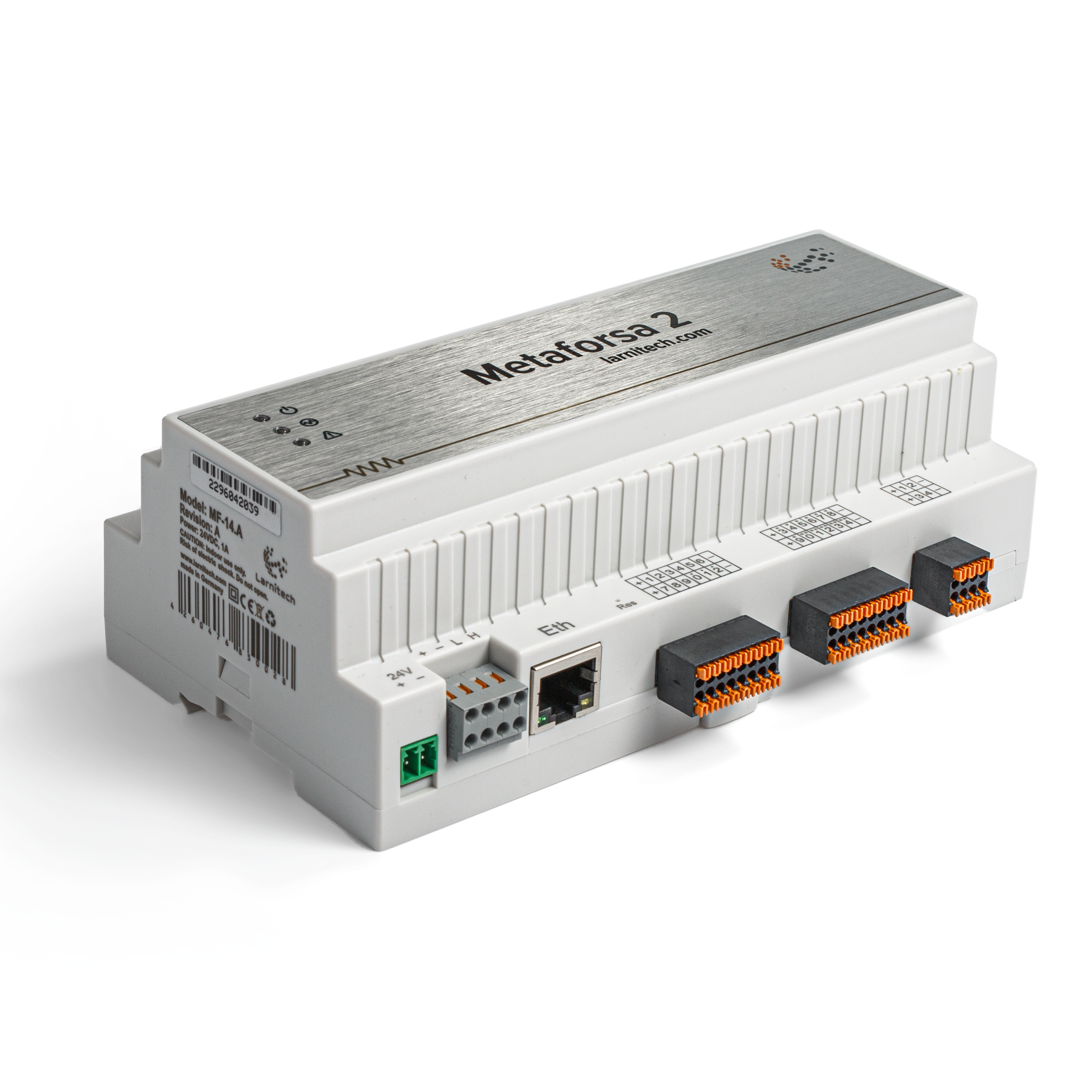
Modulets generelle visning er vist i fig. 1
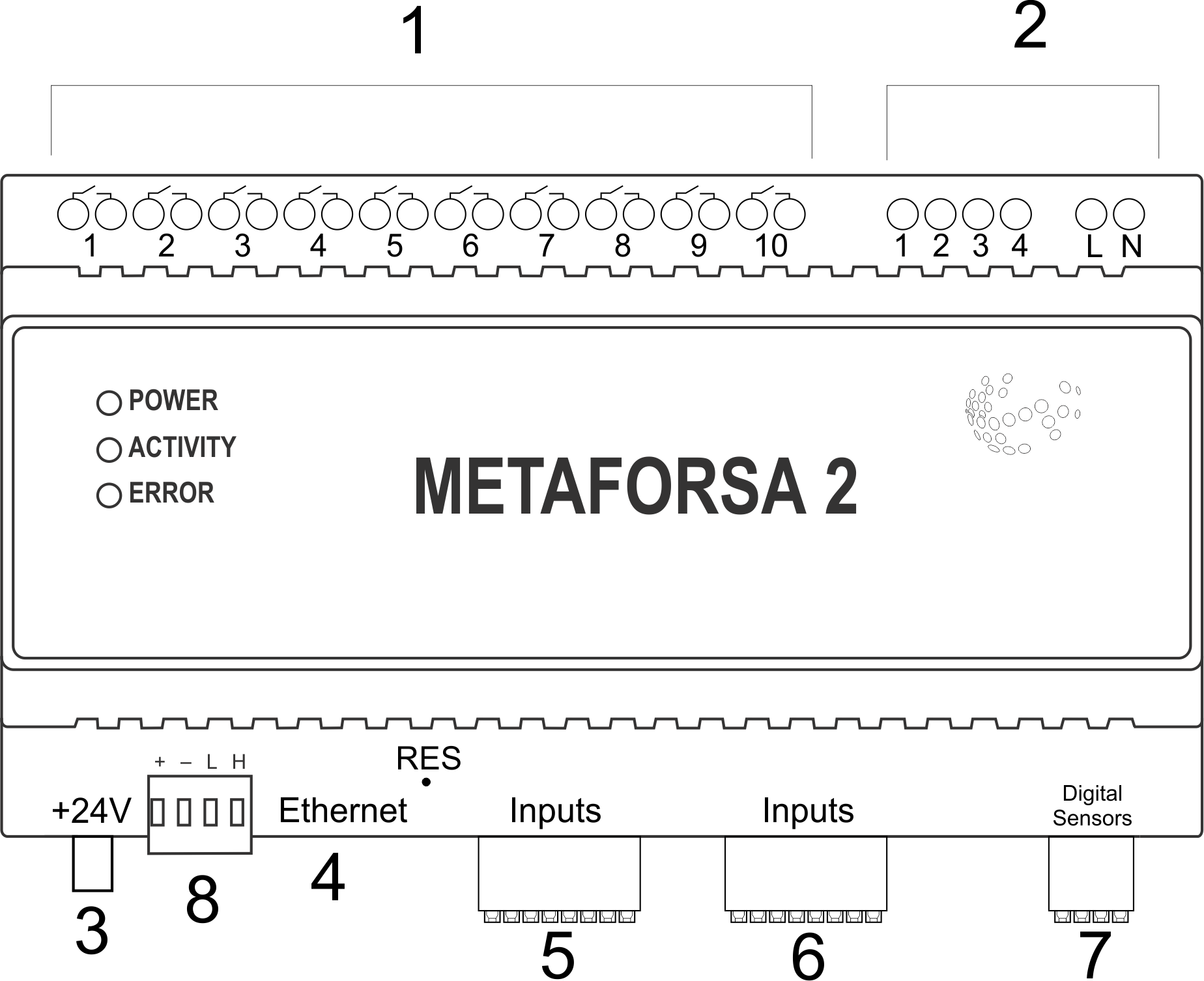
| 1 | — stik til belastningsanvendelse |
| 2 | — stik til dæmpning af lamper |
| 3 | — strømstik |
| 4 | — Ethernet-netværksstik |
| 5-6 | — stik til digitale sensorer og knapper/omskifterenheder |
| 7 | — OneWire-interfacestik (til digitale sensorer) |
| 8 | — stik til udvidelsesmodul. |
Oversigt over METAFORSA-enhedens eksterne stik:
Øverst på kabinettet (fig. 1) er der:
- stik (1) — Enhedsforbindelse;
- stik (2) — Tilslutning af dæmpende lamper;
I bunden af kabinettet (fig. 1) er der:
- stik (3) — modulstrømforsyningsforbindelse;
- stik (4) — Ethernet-netværksforbindelse;
- konnektorer (5-6) — fire sekspunktskonnektorer til tilslutning af digitale sensorer - bevægelse, lækage, reed switch-sensorer og *knap/switchende enhedssensorer;
- stik (7) — OneWire digitale sensorer busforbindelse;
- stik (8) — udvidelsesmodultilslutning.
Den fysiske konfiguration og tildeling af kontaktpunkter for hvert stik er vist i tabel 2.
| Kontakt | Kontakt | Opgave | |||||||||||||||||||||||||||||||||||||||||||||||||||||||||||||||||||||||||||||||||||||||||||||||||||||||||||||||||||||||||||||||||||||||||||||||||
|---|---|---|---|---|---|---|---|---|---|---|---|---|---|---|---|---|---|---|---|---|---|---|---|---|---|---|---|---|---|---|---|---|---|---|---|---|---|---|---|---|---|---|---|---|---|---|---|---|---|---|---|---|---|---|---|---|---|---|---|---|---|---|---|---|---|---|---|---|---|---|---|---|---|---|---|---|---|---|---|---|---|---|---|---|---|---|---|---|---|---|---|---|---|---|---|---|---|---|---|---|---|---|---|---|---|---|---|---|---|---|---|---|---|---|---|---|---|---|---|---|---|---|---|---|---|---|---|---|---|---|---|---|---|---|---|---|---|---|---|---|---|---|---|---|---|---|---|
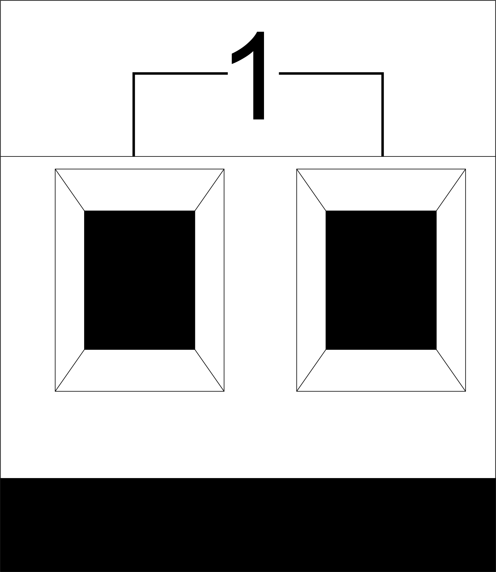 |
1-10 | Belastning (lyslamper, termiske aktuatorer osv.) | |||||||||||||||||||||||||||||||||||||||||||||||||||||||||||||||||||||||||||||||||||||||||||||||||||||||||||||||||||||||||||||||||||||||||||||||||
| D1-4, L, N | Belastningsanvendelse (dæmpende lamper) | ||||||||||||||||||||||||||||||||||||||||||||||||||||||||||||||||||||||||||||||||||||||||||||||||||||||||||||||||||||||||||||||||||||||||||||||||||
| Enhedsstatusindikatorer | Modulstatusindikatorerne er beskrevet i tabel 3 | ||||||||||||||||||||||||||||||||||||||||||||||||||||||||||||||||||||||||||||||||||||||||||||||||||||||||||||||||||||||||||||||||||||||||||||||||||
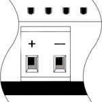 |
+24V GND |
+24V — modulstrømforsyning med en ekstern 24 V strømforsyning GND — fælles | |||||||||||||||||||||||||||||||||||||||||||||||||||||||||||||||||||||||||||||||||||||||||||||||||||||||||||||||||||||||||||||||||||||||||||||||||
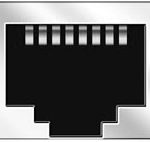 |
RJ45 | Stik til LAN-forbindelse | |||||||||||||||||||||||||||||||||||||||||||||||||||||||||||||||||||||||||||||||||||||||||||||||||||||||||||||||||||||||||||||||||||||||||||||||||
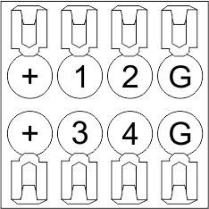
| In1-12, In13-24 GND | Tilslutning af styreenheder (knapper, magnetiske reed-kontakter, bevægelses- eller lækagesensorer): +12V — sensoreffekt +12 V In1 … In24 — logiske indgange (0-12 V) GND — fælles | ||||||||||||||||||||||||||||||||||||||||||||||||||||||||||||||||||||||||||||||||||||||||||||||||||||||||||||||||||||||||||||||||||||||||||||||||||
 |
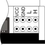
OneWire | Digital sensorforbindelse (temperatur) VCC — sensorens strømforsyningsudgang +5V OW1-OW4 — OneWire-databusser GND — fælles | |||||||||||||||||||||||||||||||||||||||||||||||||||||||||||||||||||||||||||||||||||||||||||||||||||||||||||||||||||||||||||||||||||||||||||||||||
 |
VCC GND L H |
}
Systeminstallation og monteringFør du tilslutter systemet, skal du:
ADVARSEL!
AC-strømspænding skal leveres til systemindgangen gennem afbryderenheden. Den skal installeres tæt på strømforsyningen.
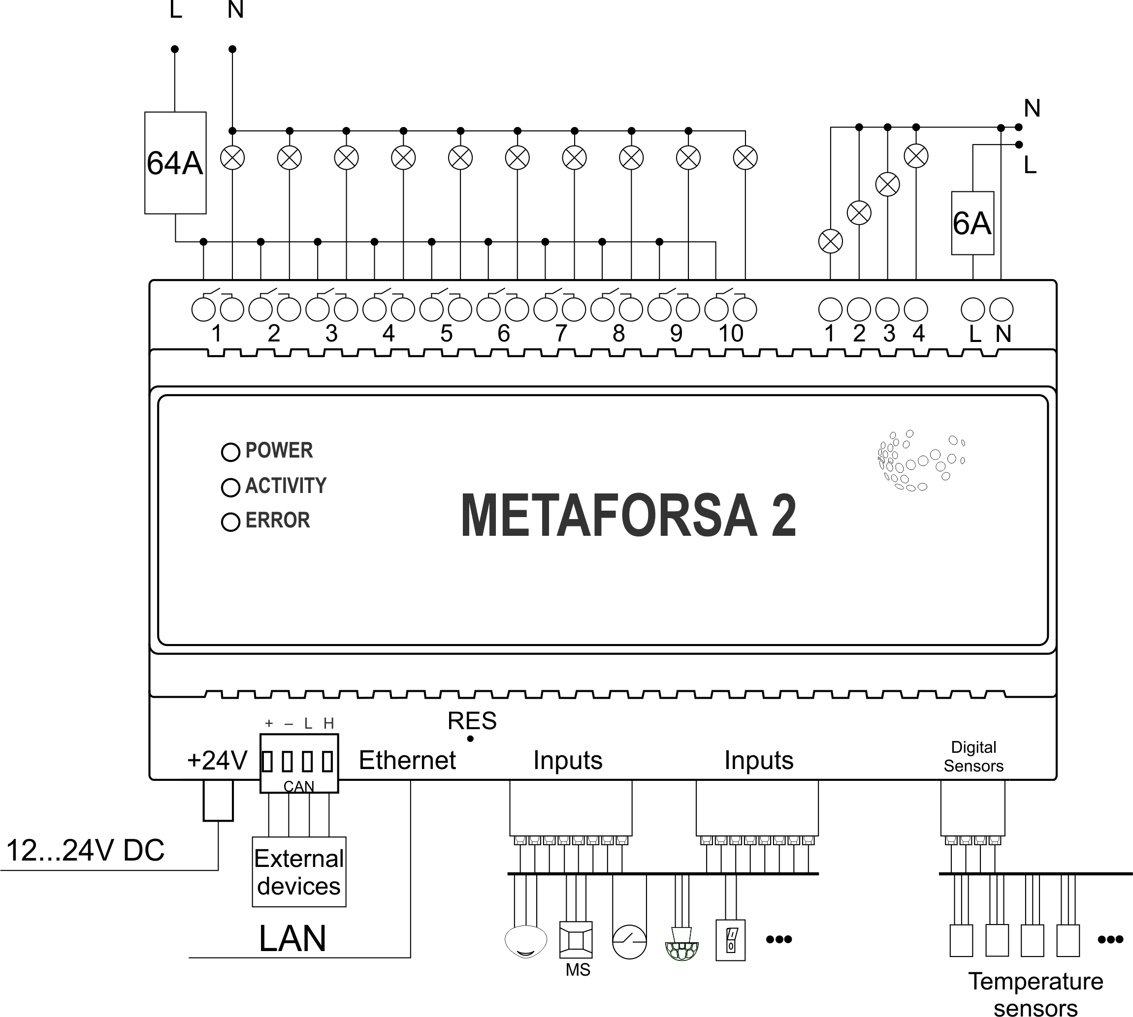
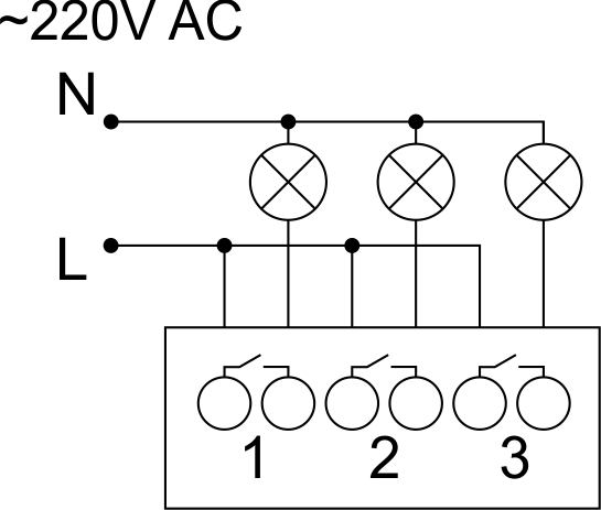
Tilslutning af aktuatorerTilslutning af lys/elektrisk kontaktor/varme-termisk aktuator
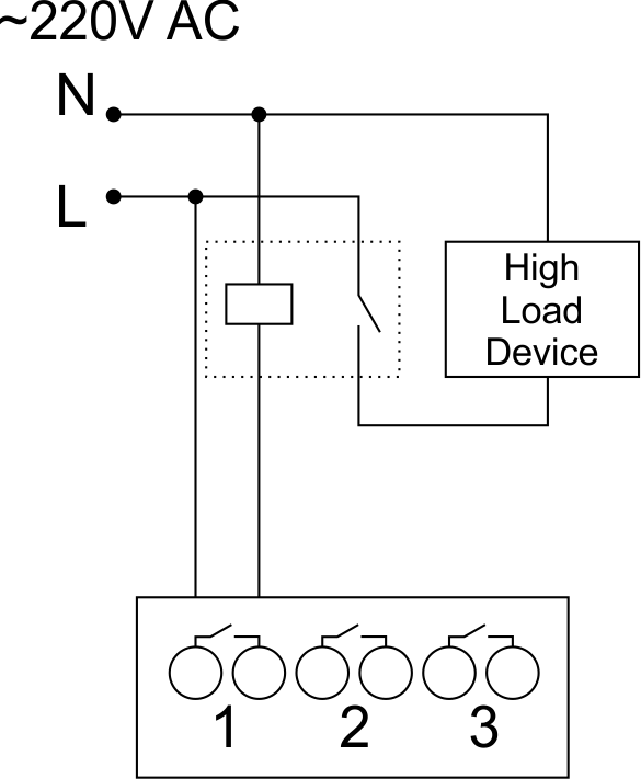
Tilslutning af højbelastningsenhed
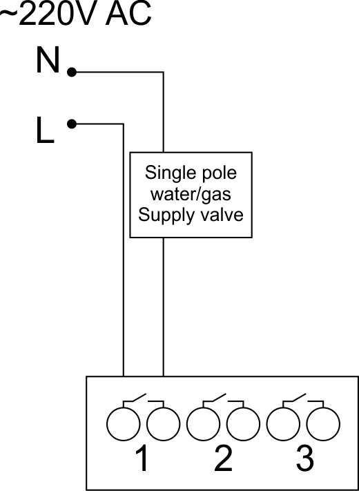
Tilslutning af enpolet vand-/gasforsyningsventil
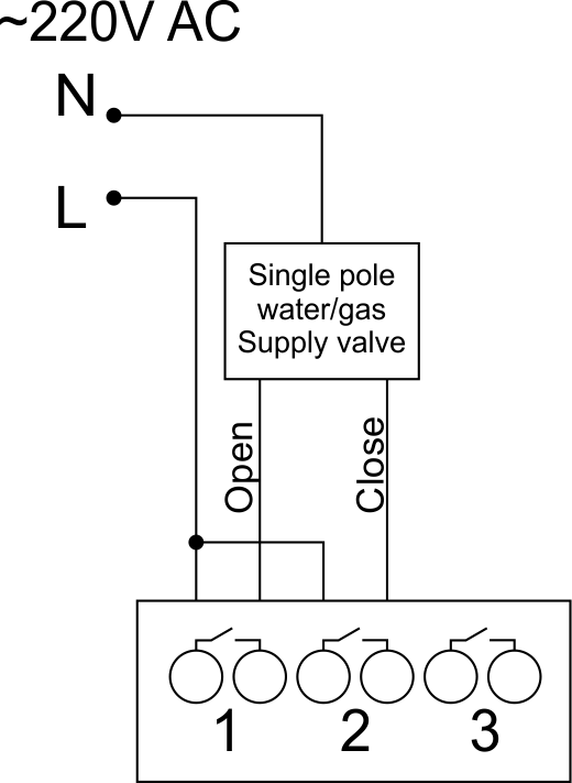
Tilslutning af dobbeltpolet vand/gas forsyningsventil
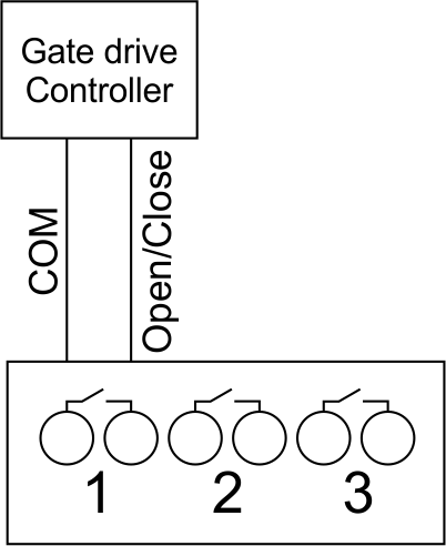
Connection of single-pole gate actuator
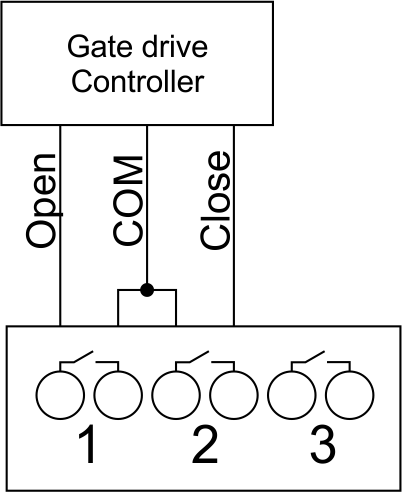
Connection of double-pole gate actuator
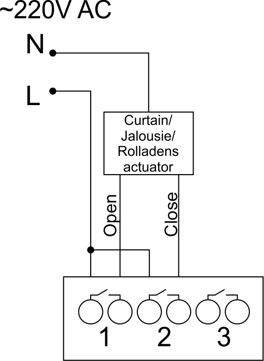
Connection of curtain/jalousie/shutter actuator with 220V force control
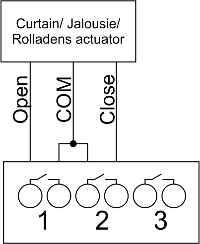
Connection of curtain/jalousie/shutter actuator with low-voltage control
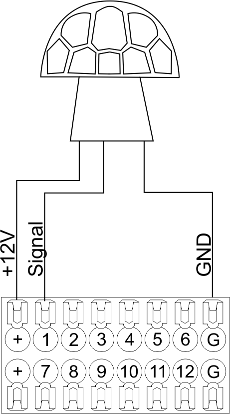
Connection of sensing elements/switches/buttonsConnection of motion sensorsThe motion sensors should be connected to any free input in1-in24; in these conditions their power is connected to the contact points of +12V and GND of the relevant group. The example of connection is shown in Fig.11.
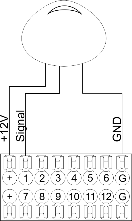
Connection of FW-WL.A leakage sensorsFW-WL.A leakage sensors are connected to any free input in1 – in24, in these conditions the power should be connected to +12V and GND points of the relevant group. The example of connection is shown in fig. 12.
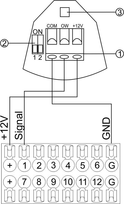
Configuration and connection of the FW-WL.A sensor 1. Terminals:
2. Sensor preset switch (optionally):
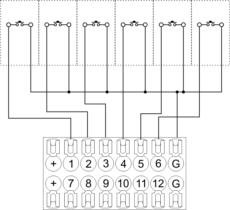
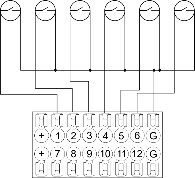
3. LED status indicator. Connection of buttons/switches/magnetic reed switchesButtons and reed switches are connected to any free input in1-in24, while their second contact point is connected to GND point of the relevant METAFORSA module group, + 12V power outputs – not in use. The example of connection is shown in Fig. 14-15.
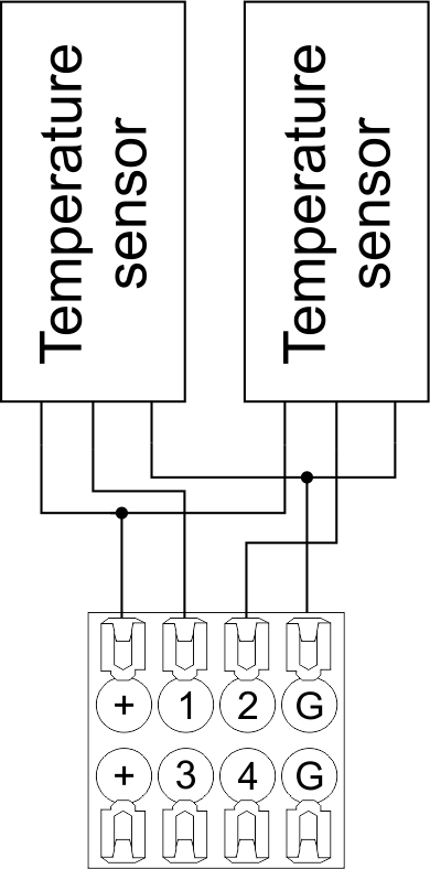
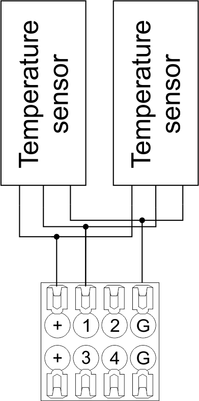
Connection of digital sensorsThe OW adapter (Fig. 16a) is supplied along with METAFORSA module with the possibility to connect up to 8 digital sensors to it. In these conditions, several devices can be connected to one channel (Fig. 16b). The connected sensors are detected automatically and do not require any original setting.
Configuration and connection of the OW adapter Caution: Ensure the connection is correct. The incorrect connection may cause sensor and/or module malfunction.
Connection of auxiliary equipment.Expansion modules include Larnitech equipment connected through the CAN-bus. Such equipment includes: dimmers, RGB-backlit control modules, multimode sensors, etc. The equipment connected to the expansion port is defined automatically and does not require any preset tuning. Connector contact pin assignment is defined in Table 4. The example of connection is shown in Fig. 17.
Module installation and connection procedure
ATTENTION! You must precisely follow the recommendations listed in the Security Requirements section hereof.
METAFORSA module shut-off and deinstallation procedure
Hardware setupTo configure and control METAFORSA SMART HOUSE, you must install Larnitech software on your smartphone or tablet, which is available in App Store and Play Market. After installation, follow the System Setup Instructions. Fault diagnostics and handlingThe following are some possible faults and ways of fault handling. If you have any difficulty, or face the fault undeclared here, please contact the Technical Support: [1] or [support@larnitech.com]. There are also some tips in the FAQ section at our website [2]. The actuators do not operate:
The module is off, indication absent:
Network connection fault:
hold integer 0-10000 1-10 by default hold is the same as runtime hold is the bridging time in miliseconds, is used for gate and jalousie, lock; Example: hold=3500
The sensors do not operate:
The auxiliary equipment does not operate:
HW Settings
 1<item addr="339:1" auto-period="600" cfgid="40" hw="def='ON'" name="Lamp" type="lamp" uniq_id="3779">
 2<item addr="339:2" cfgid="40" hw="def='ON'" name="Radiator" type="valve-heating" uniq_id="3780">
 3    <automation name="Eco" temperature-level="16" uniq_id="3781"/>
 4    <automation name="Comfort" temperature-level="22" uniq_id="3782"/>
 5    <automation name="Hot" temperature-level="25" uniq_id="3783"/>
 6</item>
 7<item addr="339:3" cfgid="40" hw="runtime=9" name="Jalousie" sub-type="120" type="jalousie" uniq_id="32"/>
 8<item addr="339:5" cfgid="40" hw="runtime=13" name="Gate" sub-type="120" type="gate" uniq_id="3784"/>
 9<item addr="339:7" cfgid="40" hw="hold=4600" name="Gate" sub-type="120" type="gate" uniq_id="3785"/>
10<item addr="339:8" cfgid="40" hw="runtime=10" name="Valve" type="valve" uniq_id="3786"/>
11<item addr="339:11" cfgid="40" name="Motion" type="motion-sensor" uniq_id="17"/>
12<item addr="339:12" cfgid="40" name="Motion" type="motion-sensor" uniq_id="18"/>
13<item addr="339:13" cfgid="40" name="Motion" type="motion-sensor" uniq_id="19"/>
14<item addr="339:16" cfgid="40" name="Leak" type="leak-sensor" uniq_id="21"/>
15<item addr="339:17" cfgid="40" name="Leak" type="leak-sensor" uniq_id="41"/>
16<item addr="339:19" cfgid="40" name="Switch" type="switch" uniq_id="22"/>
17<item addr="339:20" cfgid="40" name="Switch" type="switch" uniq_id="23"/>
18<item addr="339:21" cfgid="40" name="Switch" type="switch" uniq_id="24"/>
19<item addr="339:22" cfgid="40" name="Switch" type="switch" uniq_id="25"/>
20<item addr="339:23" cfgid="40" name="Door" type="door-sensor" uniq_id="26"/>
21<item addr="339:24" cfgid="40" name="Door" type="door-sensor" uniq_id="27"/>
22<item addr="339:25" cfgid="40" name="Door" type="door-sensor" uniq_id="28"/>
23<item addr="339:26" cfgid="40" name="Door" type="door-sensor" uniq_id="29"/>
24<item addr="339:30" cfgid="40" name="Temperature" type="temperature-sensor" uniq_id="3772"/>
25<item addr="339:31" cfgid="40" name="Temperature" type="temperature-sensor" uniq_id="3773"/>
26<item addr="339:32" cfgid="40" name="Temperature" type="temperature-sensor" uniq_id="3774"/>
27<item addr="339:33" cfgid="40" hw="offset='-10.8'" name="Temperature" type="temperature-sensor" uniq_id="3775"/>
28<item addr="339:34" cfgid="40" hw="offset='25.1'" name="Temperature" type="temperature-sensor" uniq_id="3776"/>
29<item addr="339:35" cfgid="40" name="Temperature" type="temperature-sensor" uniq_id="3777"/>
30<item addr="339:36" cfgid="40" name="Temperature" type="temperature-sensor" uniq_id="3778"/>
31<item addr="339:98" cfgid="40" hw="out='LHB-G-XV--' in='MMM--LL-BBBBKKKK'" name="Temperature" system="yes" type="temperature-sensor" uniq_id="30"/>
|
|||||||||||||||||||||||||||||||||||||||||||||||||||||||||||||||||||||||||||||||||||||||||||||||||||||||||||||||||||||||||||||||||||||||||||||||||
