Difference between revisions of "Metaforsa2 MF-14/pl"
(Created page with "700px|frameless|left|Fig. 1 Module general view <br> {| class="wikitable" style="clear:left;" |- |1 || — złącze do podłączenia obciążenia |- |2 ||...") Tags: Mobile web edit Mobile edit |
(Created page with "'''Przegląd złączy zewnętrznych urządzenia METAFORSA:''' W górnej części obudowy („rys. 1”) znajduje się:") Tags: Mobile web edit Mobile edit |
||
| Line 256: | Line 256: | ||
| − | ''' | + | '''Przegląd złączy zewnętrznych urządzenia METAFORSA:''' |
| − | + | W górnej części obudowy („rys. 1”) znajduje się: | |
Revision as of 11:43, 8 March 2024
| MF-14 | |||||||||||||
|---|---|---|---|---|---|---|---|---|---|---|---|---|---|
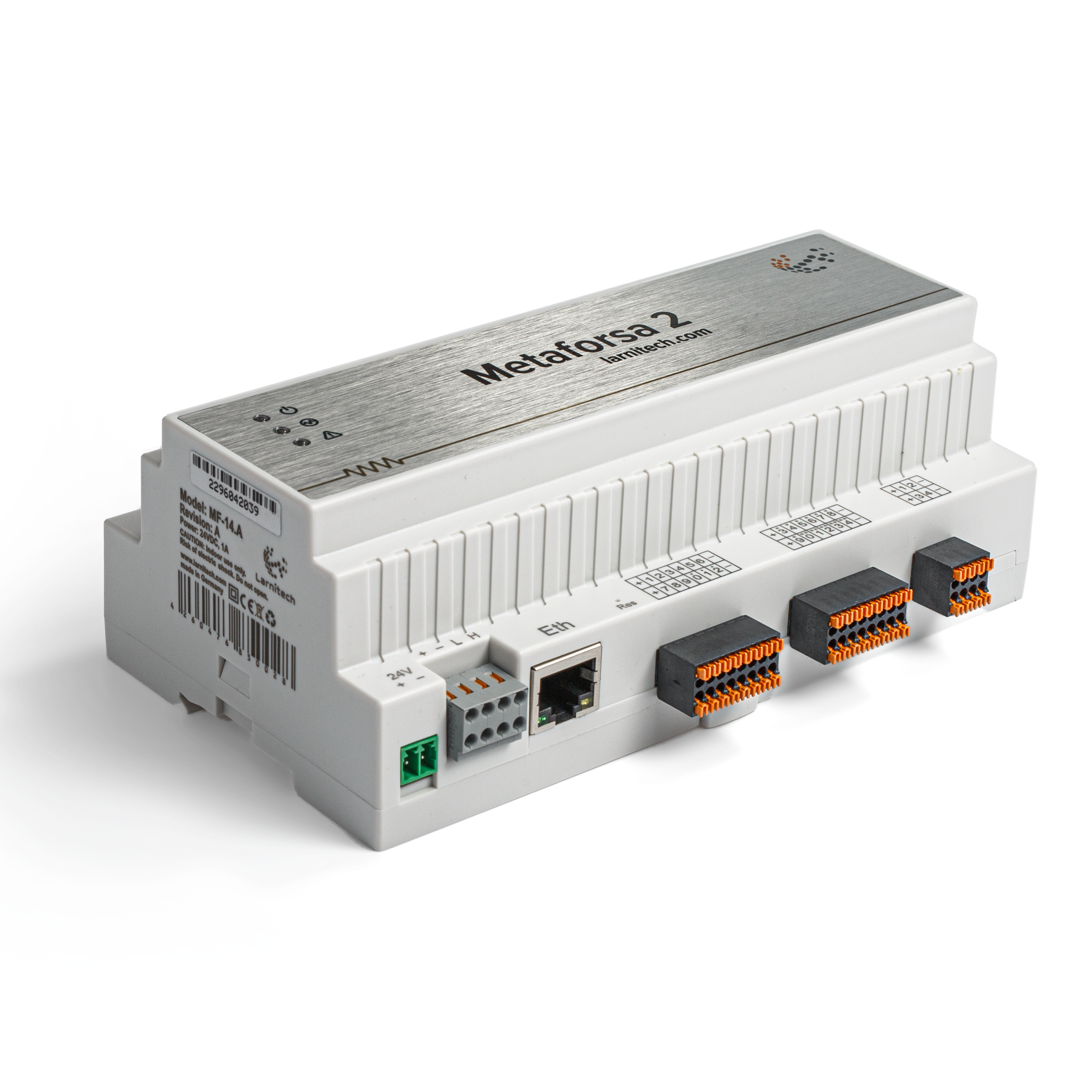 | |||||||||||||
| |||||||||||||
| |||||||||||||
| |||||||||||||
Wprowadzenie
Instrukcja instalacji METAFORSA SMART HOUSE opisuje procedurę jego instalacji, montażu, obsługi i ustawień. Podczas pracy z systemem należy bezwzględnie przestrzegać wszystkich wymagań zawartych w niniejszej instrukcji. Niezastosowanie się może skutkować uszkodzeniem urządzenia, jego awarią, porażeniem prądem, pożarem i innymi opadami atmosferycznymi. Producent zastrzega sobie prawo do wprowadzania zmian w niniejszej instrukcji bez uprzedniego powiadomienia. Niniejsza instrukcja stanowi integralną część systemu i powinna pozostać u klienta końcowego.
Cechy
- Obsługuje 10 wyjść uniwersalnych:
- Światła
- Zawory grzewcze NC/NO
- Żaluzje
- Bramy 1 lub 2-biegunowe
- Zawory 1 lub 2-biegunowe
- Zamki NC/NO
- Klimakonwektory
- 4 wyjścia ściemniające
- 24 dyskretne wejścia obsługujące:
- Guziki
- Przełączniki
- kontaktrony
- czujniki wycieków
- czujniki ruchu
- 4 wejścia cyfrowe dla maksymalnie 8 czujników temperatury
- Port rozszerzeń
- Przekaźniki ze stykami AgSnO2 o wartości znamionowej prądu rozruchowego 80 A i 20 ms
- Połączenie z chmurą i kontrola wszystkich systemów domowych
- Sterowanie głosowe (Siri, Alexa, Google Home)
- Silnik wtyczek pozwala na rozszerzenie możliwości systemu (m.in. integracja z Satel, Philips Hue, oświetleniem IKEA)
- Bezpieczeństwo przed nieupoważnionym włamaniem zapewnia szyfrowanie RSA/AES256
- Powiadomienia push z systemu na Twoim telefonie (możliwe również do odbioru za pośrednictwem komunikatorów Telegram i Viber)
- Historia (dane licznika są przechowywane przez 1 rok)
- Plug and play (możliwość szybkiej i przyjaznej dla użytkownika rozbudowy systemu)
- Regularne aktualizacje systemu
- Duża, stale aktualizowana baza skryptów, która zaspokoi wszystkie Twoje potrzeby
- Automatyczne codzienne kopie zapasowe za pośrednictwem chmury z możliwością przywrócenia początkowej konfiguracji
- Open API (umożliwiające integrację Larnitech z innymi systemami)
- Interaktywny i przyjazny dla użytkownika interfejs sieciowy LT SETUP umożliwiający zaawansowaną konfigurację
- Podłącz i graj
- Jest to całkowicie gotowy do montażu zestaw systemu Smart Home
Wymogi bezpieczeństwa
Aby uniknąć ryzyka pożaru, porażenia prądem, uszkodzenia systemu i/lub obrażeń ciała, instalację i montaż systemu należy wykonać zgodnie z poniższymi instrukcjami:
- wszystkie prace przyłączeniowe należy wykonywać bez zasilania;
- stosować odpowiednie narzędzia i środki ochrony osobistej chroniące przed porażeniem prądem;
- nie używaj uszkodzonych kabli, przewodów i złączy;
- unikaj zwijania kabli i przewodów;
- nie ściskaj ani nie zginaj kabli i przewodów poprzez użycie nadmiernej siły. W przeciwnym razie wewnętrzne żyły kabla i przewodów mogą zostać odizolowane lub uszkodzone;
- nie używaj do podłączenia gniazdka elektrycznego o słabych stykach;
- nie przekraczać limitów parametrów obciążenia określonych w niniejszej instrukcji;
- przekrój przewodów przewodów zasilających podlega specyfikacjom dotyczącym dopuszczalnej gęstości prądu, rodzaju izolacji i materiału przewodu. Sekcja świetlna może spowodować przegrzanie kabla i pożar.
Podczas pracy z systemem po podłączeniu napięcia NIGDY:
- wykonać połączenie/odłączenie złączy;
- otwarte moduły i czujniki.
Konfiguracja i przeznaczenie systemu
Cel systemu
METAFORSA SMART HOUSE to gotowe rozwiązanie do automatyzacji obiektów mieszkalnych, komercyjnych, kompleksów hotelowych, które zawiera najbardziej pożądane cechy Inteligentnego Domu.
Urządzenie posiada 10 kanałów sterujących, 4 kanały ściemniania, 24 kanały wejściowe czujników oraz port do podłączenia czujników cyfrowych.
| Wyjścia uniwersalne mogą służyć do sterowania: | Wejścia uniwersalne umożliwiają podłączenie: |
|---|---|
| Oświetlenie | Przyciski/jednostki przełączające |
| Złącza gniazdowe | Kontaktrony magnetyczne |
| Ogrzewanie podłogowe | Czujniki ruchu |
| Siłowniki kurtyn/bram | Czujniki wycieków |
| Zawory zaopatrzenia w wodę/ogrzewania |
Port podłączenia czujników cyfrowych
Port przyłączeniowy czujników cyfrowych umożliwia podłączenie różnorodnych czujników cyfrowych, takich jak czujniki temperatury, oświetlenia otoczenia, wilgotności i inne.
Port rozszerzeń
Port rozszerzeń pozwala na rozbudowę systemu poprzez podłączenie dodatkowego wyposażenia, np. modułu sterującego oświetleniem LED, ściemniania, urządzeń pomiarowych i innych elementów.
Pakiet, który jest całkowicie gotowy do instalacji, zawiera podstawowy sprzęt i oprogramowanie.
Zawartość opakowania
Pakiet jest standardowo wyposażony w:
| Komputer główny METAFORSA MF-14.А | 1 szt |
| Zasilacz MEANWELL DR-15-12 | 1 szt |
| Czujnik ruchu CW-MSD | 3 szt |
| Czujnik wycieku FW-WL.A | 2 szt |
| Element wrażliwy na temperaturę FW-TS.A | 4 szt |
| Kontaktron magnetyczny (czujnik położenia okna/drzwi) | 4 szt |
| Filtr przeciwzakłóceniowy w kablu Ethernet | 1 szt |
| Przewód zasilający | 1 szt |
Podstawowe dane techniczne Systemu
Podstawowe dane techniczne i charakterystykę modułu METAFORSA MF-14.A przedstawiono w tabeli 1
| Specyfikacja | Oznaczający |
|---|---|
| Porty wyjściowe | |
| Liczba przełączanych kanałów | 10 |
| Liczba przełączanych grup | 10 |
| Liczba kanałów ściemniania | 4 |
| Napięcie komutacyjne | 0-250 V AC/DC |
| Obciążenie szczytowe (jeden kanał) | 16A |
| Obciążenie szczytowe (urządzenie) | 160A |
| Maksymalne obciążenie na kanał ściemniania | 0,5 A (110 W przy 220 V) |
| Typ ściemniacza | MOSFET |
| Typ obciążenia ściemniacza | R, C |
| Typ ściemniania | krawędź spływu |
| Typ podłączenia kabla zasilającego | złącze |
| Dopuszczalny przekrój przewodu zasilającego do podłączenia w gniazdku: kabel jednożyłowy kabel wielożyłowy kabel wielożyłowy z końcówką |
0,5 … 4mm2 0,5 … 4mm2 0,5…2,5mm2 |
| Porty wejściowe | |
| Liczba wejść dyskretnych | 24 |
| Liczba wejść cyfrowych | 4 |
| Aktualna maksymalna wartość znamionowa złączy napięcia stałego | 50mA |
| Inne | |
| Robocza temperatura otoczenia | 0 … +45°С |
| Temperatura przechowywania/transportu | -20 … +60°С |
| Dopuszczalna wilgotność | 0 … 95% (bez kondensacji) |
| Zasilanie | 12…27,5 V DC 24 V, 0,75 A Zalecane |
| Maksymalne zapotrzebowanie | 0,5A |
| Dostępne interfejsy | Ethernet, CAN, OneWire |
| Typ autobusu | CAN (4-przewodowy) |
| CAN (4-przewodowy) | 800 m* (skrętka 5 kat) |
| Typ przewodu CAN | FTP kat. 5E |
| Typ połączenia CAN | złącze |
| Maksymalna długość linii cyfrowej | 30 m |
| Typ linii cyfrowej | UTP/FTP kat. 5E |
| Maksymalna długość sieci LAN | 100 m |
| Typ przewodu LAN | UTP/FTP kat. 5E |
| Typ połączenia LAN | Złącze RJ-45 |
| Specyfikacje wymiarowe | 9U, 156x110x58 mm |
| Materiał skorupy | Plastik ABS |
| Obudowa | IP40 |
| Typ instalacji sprzętu | Szyna DIN (EN 60715) |
| Waga | 400 gr |
* – w przypadku długich linii wymagane jest zainstalowanie dodatkowych zasilaczy; maksymalna długość linii może zostać zmniejszona przez różne czynniki zakłócające
Ogólna struktura Systemu
Ogólny widok modułu pokazano na 'rys. 1
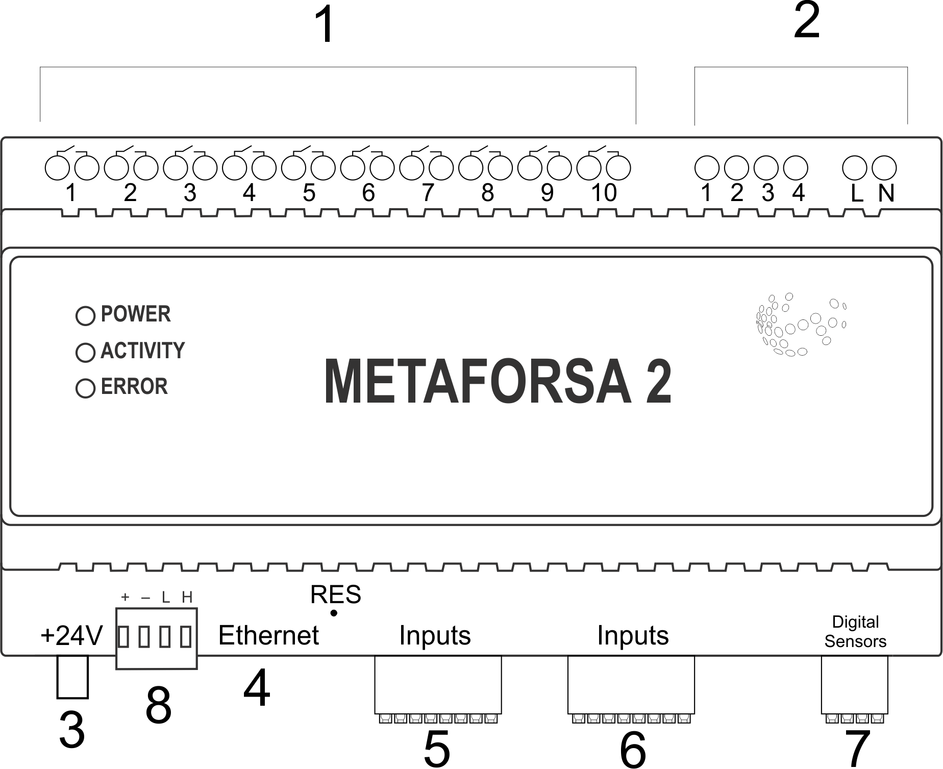
| 1 | — złącze do podłączenia obciążenia |
| 2 | — złącze do zastosowania w lampach ściemniających |
| 3 | — złącze zasilania |
| 4 | — Złącze sieci Ethernet |
| 5-6 | — złącza do czujników cyfrowych i przycisków/przełączników |
| 7 | — Złącze interfejsu OneWire (dla czujników cyfrowych) |
| 8 | — złącze modułu rozszerzeń. |
Przegląd złączy zewnętrznych urządzenia METAFORSA:
W górnej części obudowy („rys. 1”) znajduje się:
- connector (1) — Devices connection;
- connector (2) — Dimming lamps connection;
At the bottom of the casing (fig. 1) there is:
- connector (3) — module power supply connection;
- connector (4) — Ethernet network connection;
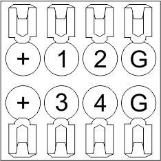
- connectors (5-6) — four six-point connectors for digital sensors connection – motion, leakage, reed switch sensors, and *button/switching unit sensors;
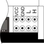
- connector (7) — OneWire digital sensors bus connection;
- connector (8) — expansion module connection.
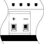
The physical configuration and contact point assignment of each connector are shown in table 2.
| Connector | Contact | Assignment |
|---|---|---|
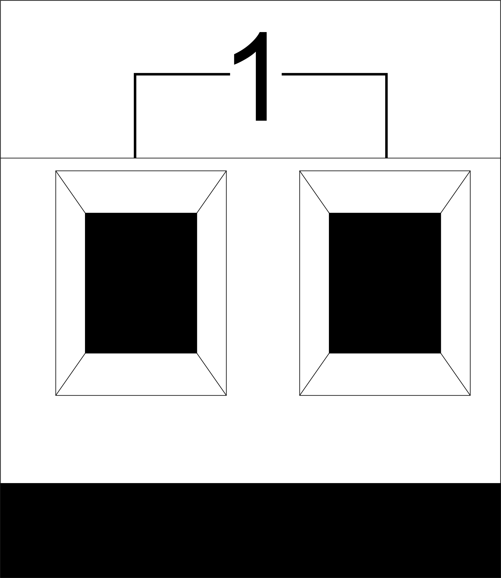 |
1-10 | Load application (light lamps, thermal actuators, etc.) |
| D1-4, L, N | Load application (dimming lamps) | |
| Device status indicators | The module status indicators are described in table 3 | |
 |
+24V GND |
+24V — module power supply by an external 24 V power supply GND — common |
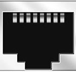 |
RJ45 | Connector for LAN connectivity |
| In1-12, In13-24 GND | Controlling devices connection (buttons, magnetic reed switches, motion or leakage sensors): +12V — sensor power output +12 V In1 … In24 — logic inputs (0-12 V) GND — common | |
 |
OneWire | Digital sensors connection (temperature) VCC — sensors power supply output +5V OW1-OW4 — OneWire data buses GND — common |
 |
VCC GND L H |
External modules connection for CAN-bus VСС — 24V output for external devices power supply GND — common L — CAN-L data bus H — CAN-H data bus |
| Indicator | Status | Description |
|---|---|---|
| Power | Power | |
| Power not available | ||
| Activity | Data communication | |
| Data communication not available | ||
| Error | No errors | |
| Communication error | ||
| Module overheat | ||
| Dimmer outputs module overload | ||
| Absence of power on dimmers, if in configuration |
System installation and assembly
Before connecting the system, you must:
- site the sensor and actuators (if not pre-installed), set the sensors and actuators;
- site the module and power supply.
Note: The module must be installed near the power supply voltage source.
- The power of circuit breaker assembly must comply with the load capacity;
- Nothing else than the phase conductors can be connected to the module, the neutral wire is connected separately.
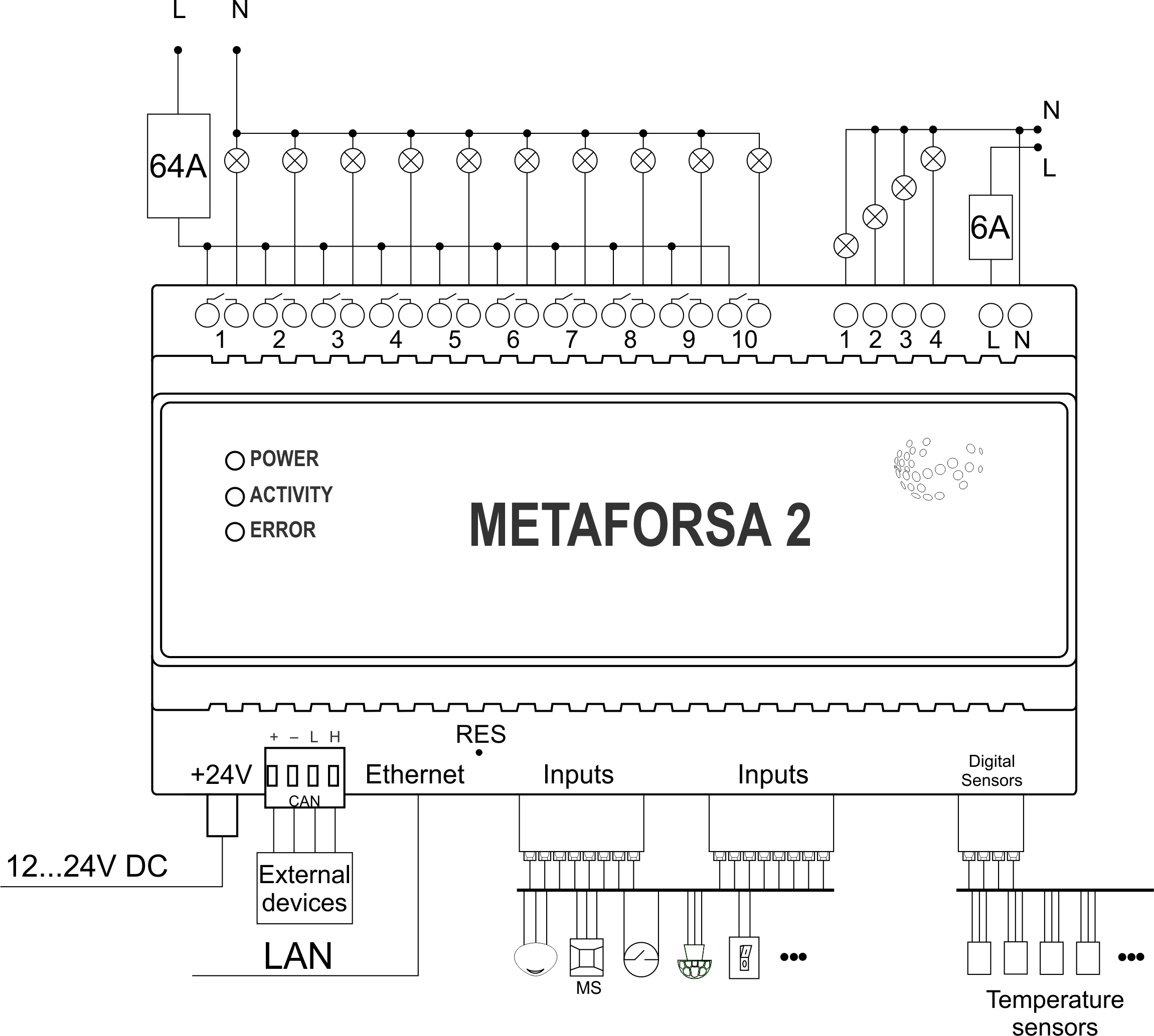
Typical diagram of METAFORSA MF-14.A module connection is shown in fig. 3.
Connection of the actuators
Connection of the lights/electric contactor/heating thermal actuator
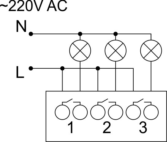 Fig. 4 |
Such actuators as light, electric contactor, heating thermal actuator should be switched on any of the outputs 1 – 10, the neutral wire and the ground wire should be connected directly to the switchboard. The example of connection is shown in Fig.4. |
Connection of high load device
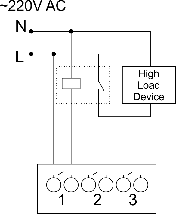 |
Recomended contactors:
|
Connection of single-pole water/gas supply valve
| Caution: Before applying power to the load, make sure that the output configuration of METAFORSA module is correct. The incorrect configuration or incorrect connection can cause the module failure and/or failure of the equipment connected to it, and even a fire. | |
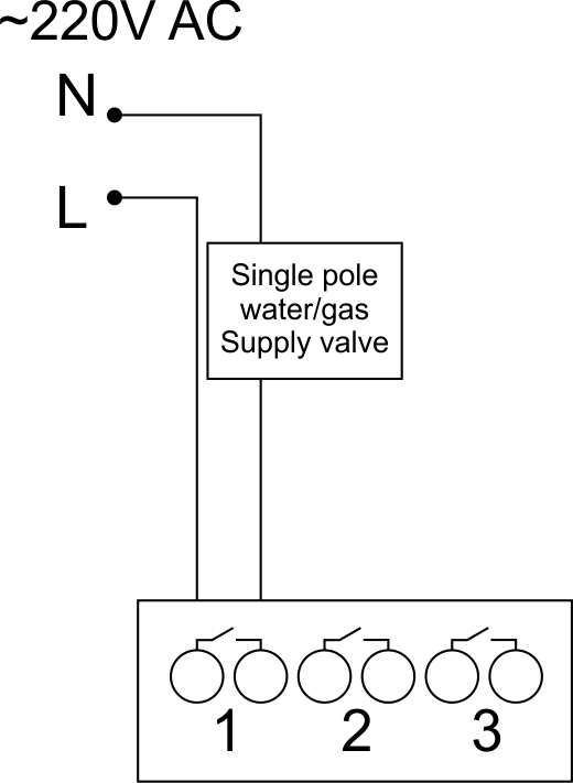 Fig. 5 |
The single pole water/gas supply valve is connected to any of the outputs of 1 – 10, the (neutral wire and the ground wire are connected directly to the switchboard. The example of connection is shown in Fig.5. |
Connection of double-pole water/gas supply valve
| Caution: Before applying power to the valve, it is necessary to ensure the output configuration of METAFORSA module is correct. The incorrect configuration can cause the voltage application simultaneously to both channels of the valve, which may result in the module failure and/or failure of the equipment connected to it, and even a fire. | |
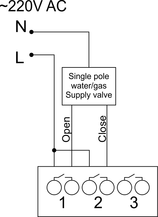 Fig. 6 |
Two adjacent contact points (for example, 3, 4) are used to connect the double-pole water/gas supply valve; in these conditions the neutral wire and the ground wire are connected directly to the switchboard. The example of connection is shown in Fig.6. |
Connection of single-pole gate actuator
| Caution: Before applying power to the module, you should properly configure access to the application. The contacts incorrectly configured can result in the module failure and/or failure of the equipment connected to it, and even a fire.
| |
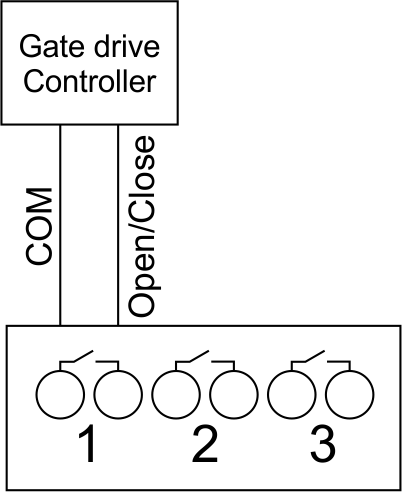 Fig. 7 |
Any contact point (for example, 3) is used to connect the single-pole gate drive controllers. The example of connection is shown in Fig.7. |
Connection of double-pole gate actuator
| Caution: Before applying power to the module, you must properly configure the outputs in the application. The contacts configured incorrectly can lead to simultaneous power supply to both channels, resulting in the module failure and/or failure of the equipment connected to it, and even a fire.
| |
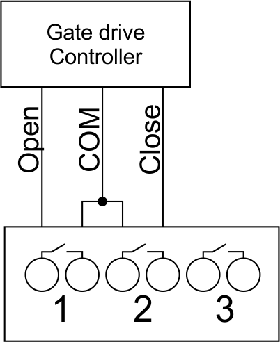 Fig. 8 |
Two adjacent contact points (for example, 3, 4) should be used to connect the double-pole gate drive controller. The example of connection is shown in Fig.8. |
Connection of curtain/jalousie/shutter actuator with 220V force control
| Caution: Before applying power to the module, you must properly configure the outputs in the application. The contacts configured incorrectly can lead to simultaneous power supply to both channels, resulting in the module failure and/or failure of the equipment connected to it, and even a fire.
| |
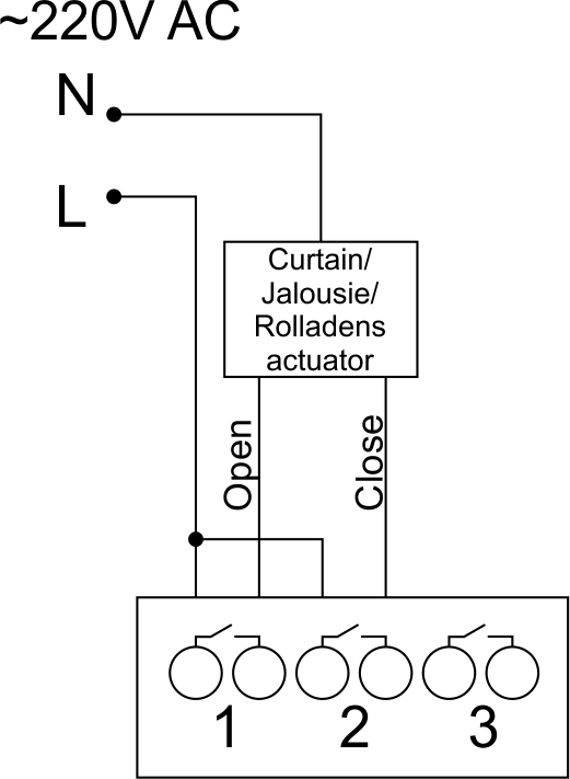 Fig. 9 |
Two adjacent contact points (for example, 3, 4) should be used to connect the curtain/jalousie/rolladens actuator, in these conditions the neutral wire and the ground wire are connected directly to the switchboard. The example of connection is shown in Fig.9. |
Connection of curtain/jalousie/shutter actuator with low-voltage control
| Caution: Before applying power to the module, you must properly configure the outputs in the application. The contacts configured incorrectly can lead to simultaneous power supply to both channels, resulting in the module failure and/or failure of the equipment connected to it, and even a fire.
| |
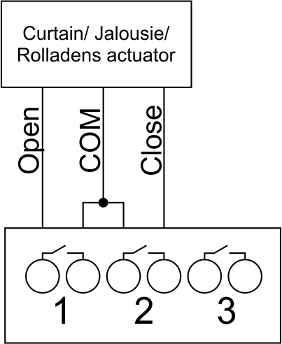 Fig. 10 |
Two adjacent contact points (for example, 3, 4) should be used to connect the curtain/jalousie/rolladens actuator with low-voltage control. The example of connection is shown in Fig.10. |
Connection of sensing elements/switches/buttons
Connection of motion sensors
The motion sensors should be connected to any free input in1-in24; in these conditions their power is connected to the contact points of +12V and GND of the relevant group. The example of connection is shown in Fig.11.
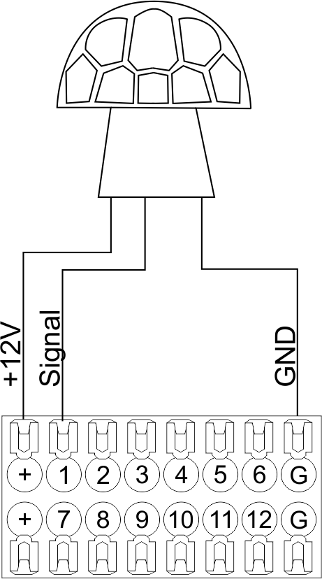
Fig. 11
Connection of FW-WL.A leakage sensors
FW-WL.A leakage sensors are connected to any free input in1 – in24, in these conditions the power should be connected to +12V and GND points of the relevant group. The example of connection is shown in fig. 12.
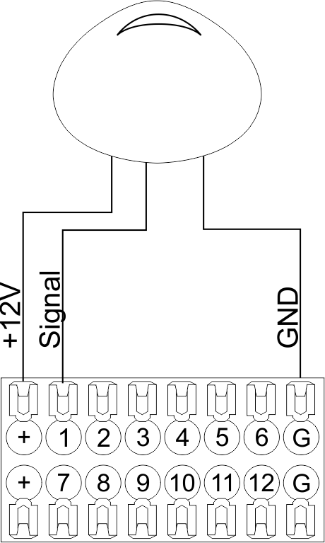 Fig12 |
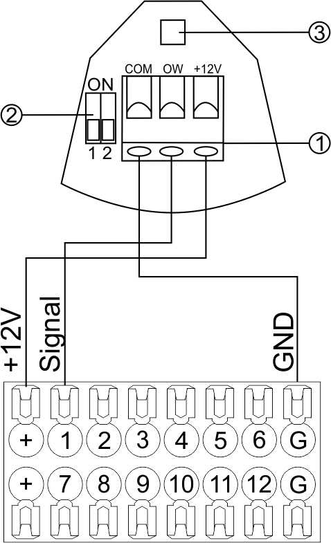 Fig13 |
Configuration and connection of the FW-WL.A sensor 1. Terminals:
- +12V — sensor power is connected to the contact point of METAFORSA “+12V”;
- OW — sensor pickup signal;
- GND — common, connected to GND contact of METAFORSA.
2. Sensor preset switch (optionally):
- 1 — sensor sensitivity (ON – high, OFF – low);
- 2 — indicator colour setting (ON – blue, OFF – green).
3. LED status indicator.
Connection of buttons/switches/magnetic reed switches
Buttons and reed switches are connected to any free input in1-in24, while their second contact point is connected to GND point of the relevant METAFORSA module group, + 12V power outputs – not in use. The example of connection is shown in Fig. 14-15.
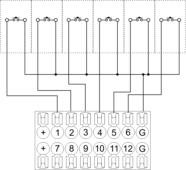 Fig14 connection of buttons/switching units |
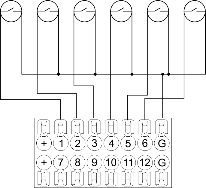 Fig15 connection of the magnetic reed switches (window/door position sensors) |
Connection of digital sensors
The OW adapter (Fig. 16a) is supplied along with METAFORSA module with the possibility to connect up to 8 digital sensors to it. In these conditions, several devices can be connected to one channel (Fig. 16b). The connected sensors are detected automatically and do not require any original setting.
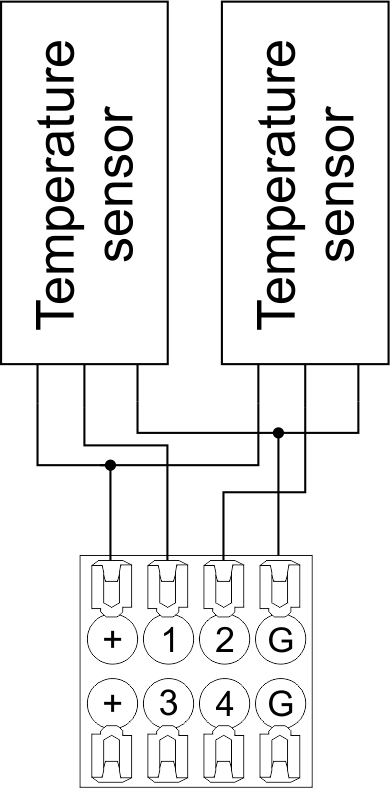 Fig16 a |
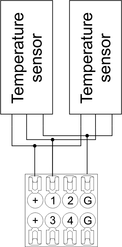 Fig16 b |
Configuration and connection of the OW adapter
Connection of auxiliary equipment.
Expansion modules include Larnitech equipment connected through the CAN-bus. Such equipment includes: dimmers, RGB-backlit control modules, multimode sensors, etc. The equipment connected to the expansion port is defined automatically and does not require any preset tuning. Connector contact pin assignment is defined in Table 4. The example of connection is shown in Fig. 17.

|
| Caution! The 120 ohm terminating resistors should be installed at the end connectors between L and H contact points of CAN-bus. Ensure the connection is correct. The incorrect connection may cause sensor and/or module malfunction. |
Module installation and connection procedure
- Install the module in the switchboard on the DIN-rail and fix it with the special latch on the module base.
- Fasten the supply unit on the left side of the module.
- Connect the connector (4) having the noise filter pre-installed which is supplied complete with the module.
- Connect the connectors (5), (6).
- Connect the connectors (1), (2).
- Connect the connector (3).
- Apply power to the supply unit of METAFORSA module.
- Wait until the module is loaded, then configure it in accordance with the System Setup Instructions.
- Apply power to the connectors (1), (2).
- Check all equipment for proper operation.
METAFORSA module shut-off and deinstallation procedure
- De-energize the module by disconnecting the circuit breaker assembly of the load power supply and METAFORSA module supply unit. Verify the voltage is absent on the terminals (1), (2) of the connector wires and on the input terminals of the supply unit.
- Disconnect the load power supply connectors (1), (2).
- Disconnect the connector (3).
- Disconnect the connectors (4)-(6).
- Remove the module from the DIN-rail, releasing the latch at the bottom of the module base.
Hardware setup
To configure and control METAFORSA SMART HOUSE, you must install Larnitech software on your smartphone or tablet, which is available in App Store and Play Market. After installation, follow the System Setup Instructions.
Fault diagnostics and handling
The following are some possible faults and ways of fault handling. If you have any difficulty, or face the fault undeclared here, please contact the Technical Support: [1] or [support@larnitech.com]. There are also some tips in the FAQ section at our website [2].
The actuators do not operate:
- ensure the outputs are properly configured in the application (see System Setup Instructions);
- check the connection is correct in accordance with table 2 and paragraph 3.6;
- ensure the power is supplied to the input power contact , i.e. all circuit breaker assembly are ON.
- verify the operability of the connected equipment.
The module is off, indication absent:
- check the connection to 24V supply unit as shown in table 2 (contacts pin assignment);
- check the connection of the supply unit to 220V power mains, the indicator should be ON.
Network connection fault:
- ensure the Ethernet cable is properly wired and connected to the connector;
- ensure the LED status indicators are ON on the Ethernet connector;
- check the LAN configuration is correct, Ethernet cable loops are absent;
- METAFORSA module and the device you are connecting from are in the same network.
hold integer 0-10000 1-10 by default hold is the same as runtime hold is the bridging time in miliseconds, is used for gate and jalousie, lock; Example: hold=3500
The sensors do not operate:
- ensure the inputs are properly configured in the application (System Setup Instructions);
- check the connection is correct in accordance with table 2 and paragraph 3.7;
- ensure the METAFORSA module is ON: circuit breaker assembly is closed, indication on the supply unit is ON, the module indication corresponds to the operating status – table 3;
- check the power supply availability on the sensors;
- check the integrity of lines laid to the sensors.
The auxiliary equipment does not operate:
- check the connection is correct in accordance with table 2 and paragraph 3.8-9;
- ensure the METAFORSA module is ON: circuit breaker assembly is closed, indication on the supply unit is ON, the module indication corresponds to the operating status – table 3;
- check the integrity of the CAN lines, voltage supply on the modules.
HW Settings
| Name | Type, range | SUBID | Default | Description |
|---|---|---|---|---|
| runtime | integer 0-100 | 1-10 | 15 | runtime is the open/close time in seconds, is used for jalousie, gate, valve(2 pole);
|
| runtimeopen | integer 0-60000 | Blinds subId | Runtimeopen is the open time in milliseconds, is used for blinds; Example: runtimeopen=15000 | |
| runtimeclose | integer 0-60000 | Blinds subId | Runtimeclose is the close time in milliseconds, is used for blinds; Example: runtimeclose=15000 | |
| hold | integer 0-10000 | 1-10 | 500 | hold is the bridging time in milliseconds, is used for gate and jalousie (by default hold is the same as runtime for jalousie and gate), lock; Example: hold=3500 |
| def | string 'ON' | 1-10 | 'OFF' | def is the element status is set after restart, is used for lamp, heating, valve(1 pole); Example: def='ON' |
| stop | Char ‘R’ | 1-7 | – | (for 2-pole gate and blinds) If it is declared then by Stop command during the motion, the same impulse appears as it was at the beginning of the motion. Pole, an which the stop-impules is formed, is defined by the parameter Stop value. If it is ‘r’ or ‘R’ then stop-impulse is produced on the opposite to the start-impulse pole. If any other value is delcared (e.g., ‘d’ ) then the stop-impulse is on the same pole. If a Runtime passed after the beginning of the motion then the stop-impulse is not formed. Example: stop=’r’ |
| out | char[10] | 98 | 'LLLLHHHHP-' | Each char is responsible for the type of a particular channel
Example: out='LLB-G-V-W-' |
| dm | char[4] | 98 | ‘LLLL’ | Each char is responsible for the type of a particular channel
Example: dm=’skl-‘ |
| def | integer 0-250 | 11-14 | 100 | The default brightness level in case of a power reset (1..250). Example: def=250 |
| min | integer 0-100 | 11-14 | 0 | Minimum dimming level, example: min=10 |
| max | integer 0-100 | 11-14 | 100 | Maximum dimming level, example max=95 |
| start | integer 0-100 | 11-14 | 0 | The Start function is used for lamps that lack the minimal voltage to get turned on. If the set value is lower than the start value, the lamp is turned on at the start value and them the light is dimmed down to the set level. Example: start=60 |
| force | integer 0-100 | 11-14 | 10 | Time duration of the starting value (measured in milliseconds). Example: force=20 |
| runtime | integer 0-60000 | 11-14 | 1000 | Runtime is the speed of changing the brightness from ‘min’ to ‘max’ (measured in milliseconds). Example: runtime=1000 |
| offset | integer (+/- 0…39) | 39-46 | '0' | sensor values offset; For example, offset is -3.8 :
Example: hw="offset='-3.8'" |
| in | char[24] | 98 | 'BBBBBBBBBBBBMMMLLLKKKKKK' | Each char is responsible for the type of a particular channel
Example: in='MMMMMMMMMMMMLLLLLLLLLLLL' 12 motion sensors and 12 leak-sensors; in='BBBBBBBBSSSSSSBBBBSSSSSS' 12 buttons; 12 switches. |
 1<item addr="339:1" auto-period="600" cfgid="40" hw="def='ON'" name="Lamp" type="lamp" uniq_id="3779">
 2<item addr="339:2" cfgid="40" hw="def='ON'" name="Radiator" type="valve-heating" uniq_id="3780">
 3    <automation name="Eco" temperature-level="16" uniq_id="3781"/>
 4    <automation name="Comfort" temperature-level="22" uniq_id="3782"/>
 5    <automation name="Hot" temperature-level="25" uniq_id="3783"/>
 6</item>
 7<item addr="339:3" cfgid="40" hw="runtime=9" name="Jalousie" sub-type="120" type="jalousie" uniq_id="32"/>
 8<item addr="339:5" cfgid="40" hw="runtime=13" name="Gate" sub-type="120" type="gate" uniq_id="3784"/>
 9<item addr="339:7" cfgid="40" hw="hold=4600" name="Gate" sub-type="120" type="gate" uniq_id="3785"/>
10<item addr="339:8" cfgid="40" hw="runtime=10" name="Valve" type="valve" uniq_id="3786"/>
11<item addr="339:11" cfgid="40" name="Motion" type="motion-sensor" uniq_id="17"/>
12<item addr="339:12" cfgid="40" name="Motion" type="motion-sensor" uniq_id="18"/>
13<item addr="339:13" cfgid="40" name="Motion" type="motion-sensor" uniq_id="19"/>
14<item addr="339:16" cfgid="40" name="Leak" type="leak-sensor" uniq_id="21"/>
15<item addr="339:17" cfgid="40" name="Leak" type="leak-sensor" uniq_id="41"/>
16<item addr="339:19" cfgid="40" name="Switch" type="switch" uniq_id="22"/>
17<item addr="339:20" cfgid="40" name="Switch" type="switch" uniq_id="23"/>
18<item addr="339:21" cfgid="40" name="Switch" type="switch" uniq_id="24"/>
19<item addr="339:22" cfgid="40" name="Switch" type="switch" uniq_id="25"/>
20<item addr="339:23" cfgid="40" name="Door" type="door-sensor" uniq_id="26"/>
21<item addr="339:24" cfgid="40" name="Door" type="door-sensor" uniq_id="27"/>
22<item addr="339:25" cfgid="40" name="Door" type="door-sensor" uniq_id="28"/>
23<item addr="339:26" cfgid="40" name="Door" type="door-sensor" uniq_id="29"/>
24<item addr="339:30" cfgid="40" name="Temperature" type="temperature-sensor" uniq_id="3772"/>
25<item addr="339:31" cfgid="40" name="Temperature" type="temperature-sensor" uniq_id="3773"/>
26<item addr="339:32" cfgid="40" name="Temperature" type="temperature-sensor" uniq_id="3774"/>
27<item addr="339:33" cfgid="40" hw="offset='-10.8'" name="Temperature" type="temperature-sensor" uniq_id="3775"/>
28<item addr="339:34" cfgid="40" hw="offset='25.1'" name="Temperature" type="temperature-sensor" uniq_id="3776"/>
29<item addr="339:35" cfgid="40" name="Temperature" type="temperature-sensor" uniq_id="3777"/>
30<item addr="339:36" cfgid="40" name="Temperature" type="temperature-sensor" uniq_id="3778"/>
31<item addr="339:98" cfgid="40" hw="out='LHB-G-XV--' in='MMM--LL-BBBBKKKK'" name="Temperature" system="yes" type="temperature-sensor" uniq_id="30"/>