Difference between revisions of "Metaforsa2 MF-14/sr"
Tags: Mobile web edit Mobile edit |
Tags: Mobile web edit Mobile edit |
||
| Line 77: | Line 77: | ||
| − | + | Kada radite sa sistemom nakon napajanja naponom '''NIKAD''': | |
| − | * | + | *izvršiti spajanje/isključivanje konektora; |
| − | * | + | *otvoreni moduli i senzori. |
==Konfihuratsiya ta pryznachennya systemy== | ==Konfihuratsiya ta pryznachennya systemy== | ||
Revision as of 07:48, 12 March 2024
| MF-14 | |||||||||||||
|---|---|---|---|---|---|---|---|---|---|---|---|---|---|
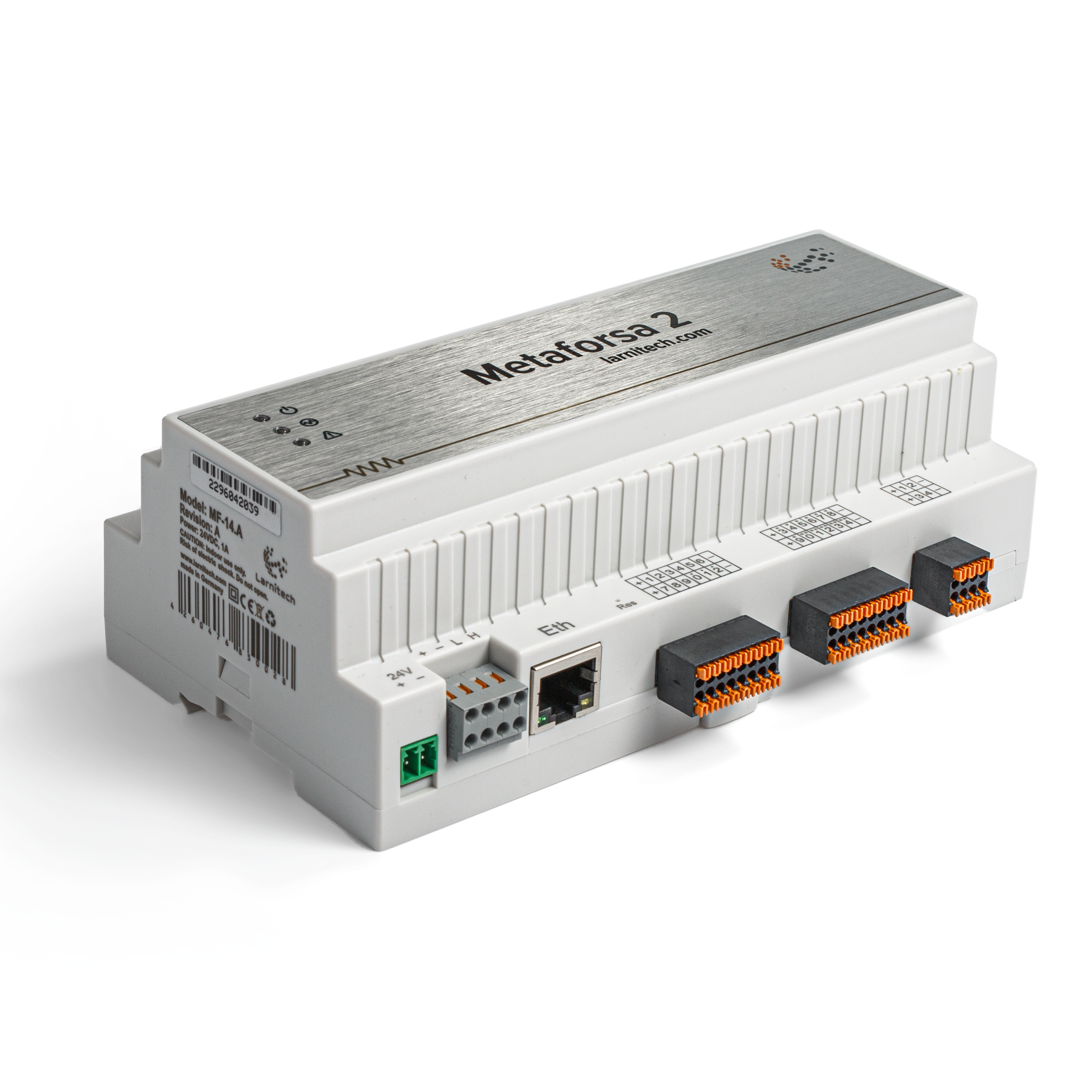 | |||||||||||||
| |||||||||||||
| |||||||||||||
| |||||||||||||
Uvod
Instruktsiya z montazhu METAFORSA SMART HOUSE opysuye poryadok yoho montazhu, montazhu, ekspluatatsiyi ta nalashtuvannya. Pry roboti z systemoyu neobkhidno suvoro dotrymuvatysya vsikh vymoh, vykladenykh u tsiy instruktsiyi. Nedotrymannya mozhe pryzvesty do poshkodzhennya prystroyu, yoho polomky, urazhennya elektrychnym strumom, pozhezhi ta inshykh naslidkiv. Vyrobnyk zalyshaye za soboyu pravo vnosyty zminy v tsey posibnyk bez poperednʹoho povidomlennya. Tsey posibnyk ye nevidʺyemnoyu chastynoyu systemy ta maye zalyshatysya u kintsevoho korystuvacha.
Karakteristike
- Podržava 10 univerzalnih izlaza:
- Lights
- NC/NO ventili za grejanje
- Blinds
- 1 ili 2-polne kapije
- 1 ili 2-polni ventili
- NC/NO brave
- Fan coil jedinice
- 4 izlaza za zatamnjivanje
- 24 diskretna ulaza koji podržavaju:
- Dugmad
- Prekidači
- prekidači
- senzori curenja
- detektori pokreta
- 4 digitalna ulaza za do 8 temperaturnih senzora
- Priključak za proširenje
- Releji sa AgSnO2 kontaktima predviđeni za udarnu struju od 80A 20ms
- Klaud veza i kontrola svih kućnih sistema
- Upravljanje glasom (Siri, Aleka, Google Home)
- Plugins engine omogućava proširenje mogućnosti sistema (npr. integracija sa Satel, Philips Hue, IKEA lampama)
- Sigurnost od neovlašćenog upada osigurana RSA/AES256 enkripcijom
- Push obaveštenja iz sistema na vašem telefonu (moguće je i primanje preko Telegram i Viber mesindžera)
- Istorija (podaci brojila za godinu dana se čuvaju)
- Plug and plai (mogućnost brzog i jednostavnog proširenja sistema)
- Redovna ažuriranja sistema
- Velika baza skripti koja se stalno ažurira kako bi zadovoljila sve vaše potrebe
- Automatsko dnevno pravljenje rezervnih kopija preko oblaka sa mogućnošću vraćanja početne konfiguracije
- Otvoreni API (koji omogućava integraciju Larnitech-a u druge sisteme)
- Interaktivan i prilagođen korisniku LT SETUP Veb interfejs dostupan za naprednu konfiguraciju
- Plug and plai
- To je komplet sistema Smart Home spreman za instalaciju
Zahtevi za bezbednost
Da biste izbegli rizik od požara, strujnog udara, oštećenja sistema i/ili ličnih povreda, instalacija i montaža sistema se moraju izvršiti u skladu sa uputstvima navedenim u nastavku:
- svi radovi na priključenju moraju se izvoditi bez struje;
- koristite odgovarajući alat i ličnu zaštitu od strujnog udara;
- ne koristite oštećene kablove, žice i konektore;
- izbegavajte savijanje kablova i žica;
- nemojte štipati ili savijati kablove i žice primenom prekomerne sile. U suprotnom, unutrašnji provodnici kabla i žica mogu biti ogoljeni ili slomljeni;
- za povezivanje nemojte koristiti utičnicu sa lošim kontaktima;
- ne prekoračite ograničenje parametara opterećenja navedeno u ovom priručniku;
- presek žice provodnika za napajanje podleže specifikacijama za ograničenje gustine struje, tip izolacije i materijal žice. Lagani deo može dovesti do pregrevanja kabla i požara.
Kada radite sa sistemom nakon napajanja naponom NIKAD:
- izvršiti spajanje/isključivanje konektora;
- otvoreni moduli i senzori.
Konfihuratsiya ta pryznachennya systemy
Pryznachennya systemy
METAFORSA SMART HOUSE — tse hotove rishennya dlya avtomatyzatsiyi zhytlovykh i komertsiynykh prymishchenʹ, hotelʹnykh kompleksiv, yake vklyuchaye v sebe naybazhanishi mozhlyvosti Smart House.
Prystriy maye 10 kanaliv upravlinnya, 4 kanaly dymmuvannya, 24 vkhidnykh sensornykh kanalu, port pidklyuchennya tsyfrovykh datchykiv.
| Universalʹni vykhody mozhna vykorystovuvaty dlya upravlinnya: | Universalʹni vkhody dozvolyayutʹ pidklyuchaty: |
|---|---|
| Osvitlennya | Knopky/bloky peremykannya |
| Rozetkovi z'yednuvachi | Mahnitni herkony |
| Pidihriv pidlohy | Datchyky rukhu |
| Pryvody shtor/vorit | Datchyky protikannya |
| Klapany vodopostachannya/opalennya |
Port pidklyuchennya tsyfrovykh datchykiv
Port pidklyuchennya tsyfrovykh datchykiv dozvolyaye pidklyuchaty riznomanitni tsyfrovi datchyky, taki yak datchyky temperatury, zovnishnʹoho osvitlennya, volohosti toshcho.
Port rozshyrennya
Port rozshyrennya dozvolyaye modernizuvaty systemu shlyakhom pidklyuchennya dopomizhnoho obladnannya, takoho yak modulʹ upravlinnya svitlodiodnym osvitlennyam, dymmuvannya, prylady obliku ta inshi elementy.
Paket, yakyy povnistyu hotovyy do vstanovlennya, vklyuchaye bazove aparatne ta prohramne zabezpechennya.
Vmist upakovky
U standartnu komplektatsiyu vkhodytʹ:
| Meynfreym METAFORSA MF-14.A | 1 sht |
| Blok zhyvlennya MEANWELL DR-15-12 | 1 sht |
| Datchyk rukhu CW-MSD | 3 sht |
| Datchyk protikannya FW-WL.A | 2 sht |
| Termochutlyvyy element FW-TS.A | 4 sht |
| Mahnitnyy herkon (datchyk polozhennya vikna/dveri) | 4 sht |
| Filʹtr pereshkod Ethernet-kabelyu | 1 sht |
| Shnur zhyvlennya | 1 sht |
Osnovni tekhnichni kharakterystyky Systemy
Osnovni tekhnichni kharakterystyky ta kharakterystyky modulya METAFORSA MF-14.A navedeni v tablytsi 1
| Spetsyfikatsiya | Znachennya |
|---|---|
| 'Vykhidni porty' | |
| Kilʹkistʹ komutovanykh kanaliv | 10 |
| Kilʹkistʹ pereklyuchenykh hrup | 10 |
| Kilʹkistʹ kanaliv zatemnennya | 4 |
| Napruha komutatsiyi | 0-250 V zminnoho/postiynoho strumu |
| Pikove navantazhennya (odyn kanal) | 16A |
| Pikove navantazhennya (prylad) | 160A |
| Maksymalʹne navantazhennya na kanal dymmuvannya | 0,5 A (110 Vt pry 220 V) |
| Typ dymmera | MOSFET |
| Typ navantazhennya dymmera | R,C |
| Typ zatemnennya | zadniy kray |
| Typ pidklyuchennya kabelyu zhyvlennya | roz'yem |
| Dopustymyy peretyn kabelyu zhyvlennya dlya pidklyuchennya do rozetky: odnozhylʹnyy kabelʹ bahatozhylʹnyy kabelʹ bahatozhylʹnyy kabelʹ z nakonechnykom |
0,5 … 4 mm2 0,5 … 4 mm2 0,5 … 2,5 mm2 |
| 'Vkhidni porty' | |
| Kilʹkistʹ dyskretnykh vkhodiv | 24 |
| Kilʹkistʹ tsyfrovykh vkhodiv | 4 |
| Maksymalʹnyy strum na roz'yemakh postiynoyi napruhy | 50 mA |
| 'Inshe' | |
| Robocha temperatura navkolyshnʹoho seredovyshcha | 0 … +45°S |
| Temperatura zberihannya/transportuvannya | -20 … +60°S |
| Dopustyma volohistʹ | 0 … 95% (bez kondensatsiyi) |
| Elektropostachannya | 12 … 27,5 V postiynoho strumu 24 V, 0,75 A rekomendovano |
| Maksymalʹnyy popyt | 0,5A |
| Dostupni interfeysy | Ethernet, CAN, OneWire |
| Typ avtobusa | CAN (4-providnyy) |
| CAN (4-providnyy) | 800 m* (kruchena para 5 kot.) |
| Typ provodu CAN | FTP Cat 5E |
| Typ pidklyuchennya CAN | roz'yem |
| Maksymalʹna dovzhyna tsyfrovoyi liniyi | 30 m |
| Tsyfrova liniya Wirde typu | UTP/FTP Cat 5E |
| maksymalʹna dovzhyna lokalʹnoyi merezhi | 100 m |
| Typ provodu LAN | UTP/FTP Cat 5E |
| Typ pidklyuchennya LAN | Roz'yem RJ-45 |
| Habarytni kharakterystyky | 9U, 156x110x58 mm |
| Material obolonky | ABS plastyk |
| Obshyvka | IP40 |
| Typ ustanovky obladnannya | DIN-reyka (EN 60715) |
| Vaha | 400 h |
* – dlya dovhykh liniy potribna ustanovka dodatkovykh blokiv zhyvlennya; maksymalʹna dovzhyna liniyi mozhe buty zmenshena riznymy faktoramy pereshkod
Zahalʹna struktura Systemy
Zahalʹnyy vyhlyad modulya pokazano na mal. 1
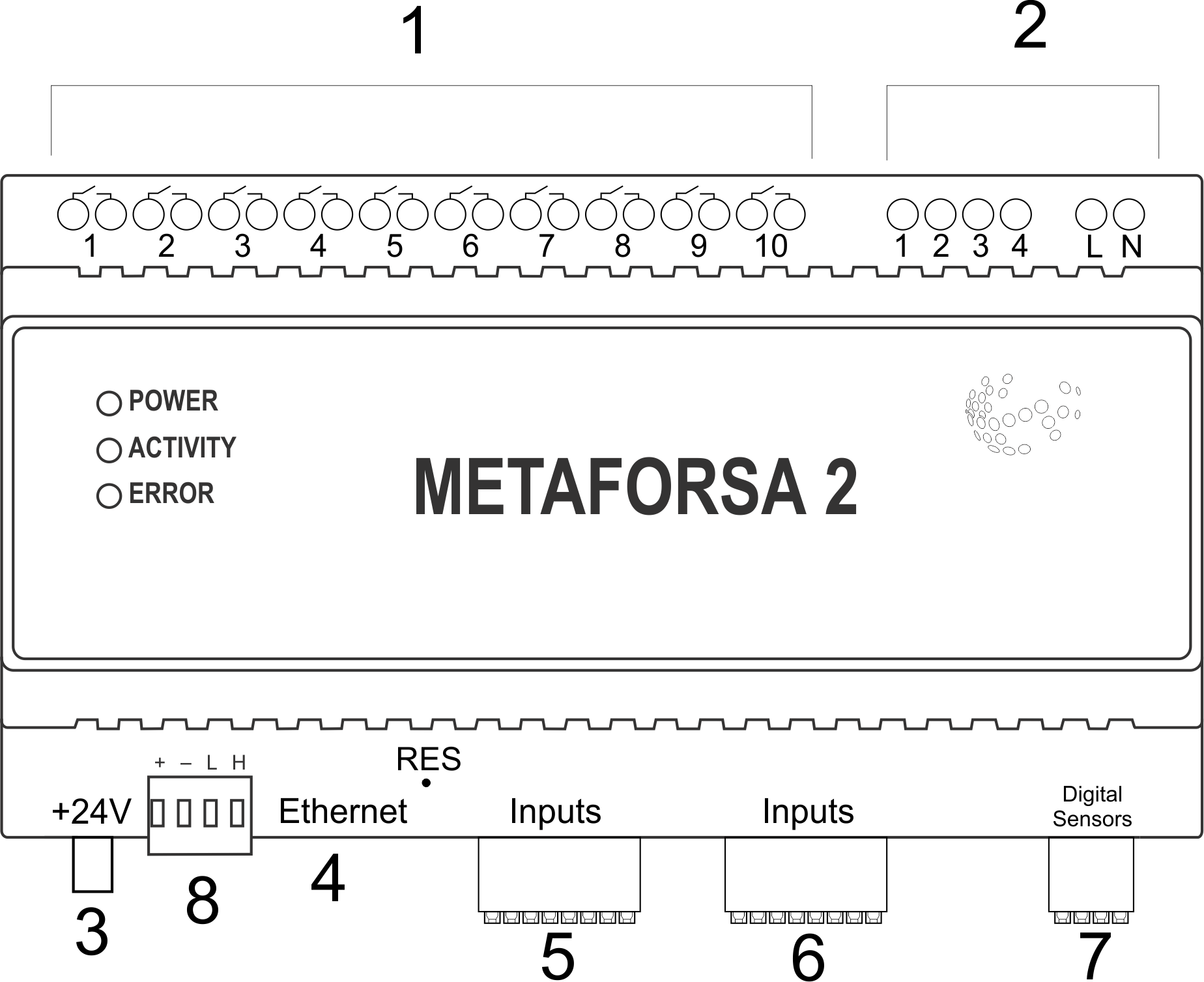
| 1 | — connector for load application |
| 2 | — connector for dimming-lamps application |
| 3 | — power connector |
| 4 | — Ethernet network connector |
| 5-6 | — connectors for digital sensors and buttons/switching units |
| 7 | — OneWire interface connector (for digital sensors) |
| 8 | — connector for expansion module. |
Overview of the METAFORSA device external connectors:
At the top of the casing (fig. 1) there is:
- connector (1) — Devices connection;
- connector (2) — Dimming lamps connection;
At the bottom of the casing (fig. 1) there is:
- connector (3) — module power supply connection;
- connector (4) — Ethernet network connection;
- connectors (5-6) — four six-point connectors for digital sensors connection – motion, leakage, reed switch sensors, and *button/switching unit sensors;
- connector (7) — OneWire digital sensors bus connection;
- connector (8) — expansion module connection.
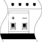
The physical configuration and contact point assignment of each connector are shown in table 2.
| Connector | Contact | Assignment |
|---|---|---|
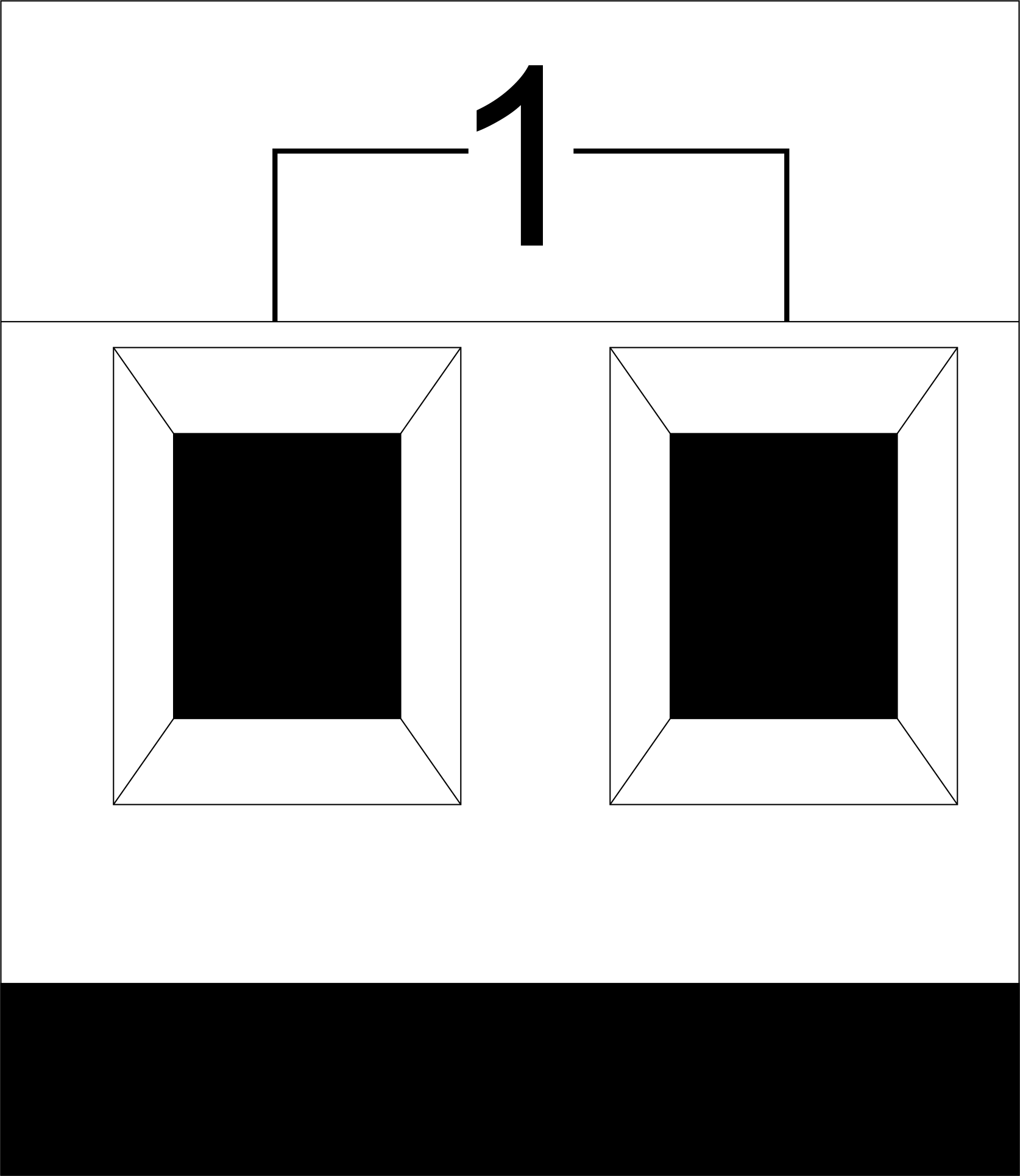 |
1-10 | Load application (light lamps, thermal actuators, etc.) |
| D1-4, L, N | Load application (dimming lamps) | |
| Device status indicators | The module status indicators are described in table 3 | |
 |
+24V GND |
+24V — module power supply by an external 24 V power supply GND — common |
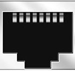 |
RJ45 | Connector for LAN connectivity |
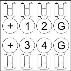
| In1-12, In13-24 GND | Controlling devices connection (buttons, magnetic reed switches, motion or leakage sensors): +12V — sensor power output +12 V In1 … In24 — logic inputs (0-12 V) GND — common | |
 |
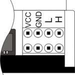
OneWire | Digital sensors connection (temperature) VCC — sensors power supply output +5V OW1-OW4 — OneWire data buses GND — common |
 |
VCC GND L H |
External modules connection for CAN-bus VСС — 24V output for external devices power supply GND — common L — CAN-L data bus H — CAN-H data bus |
| Indicator | Status | Description |
|---|---|---|
| Power | Power | |
| Power not available | ||
| Activity | Data communication | |
| Data communication not available | ||
| Error | No errors | |
| Communication error | ||
| Module overheat | ||
| Dimmer outputs module overload | ||
| Absence of power on dimmers, if in configuration |
System installation and assembly
Before connecting the system, you must:
- site the sensor and actuators (if not pre-installed), set the sensors and actuators;
- site the module and power supply.
Note: The module must be installed near the power supply voltage source.
- The power of circuit breaker assembly must comply with the load capacity;
- Nothing else than the phase conductors can be connected to the module, the neutral wire is connected separately.
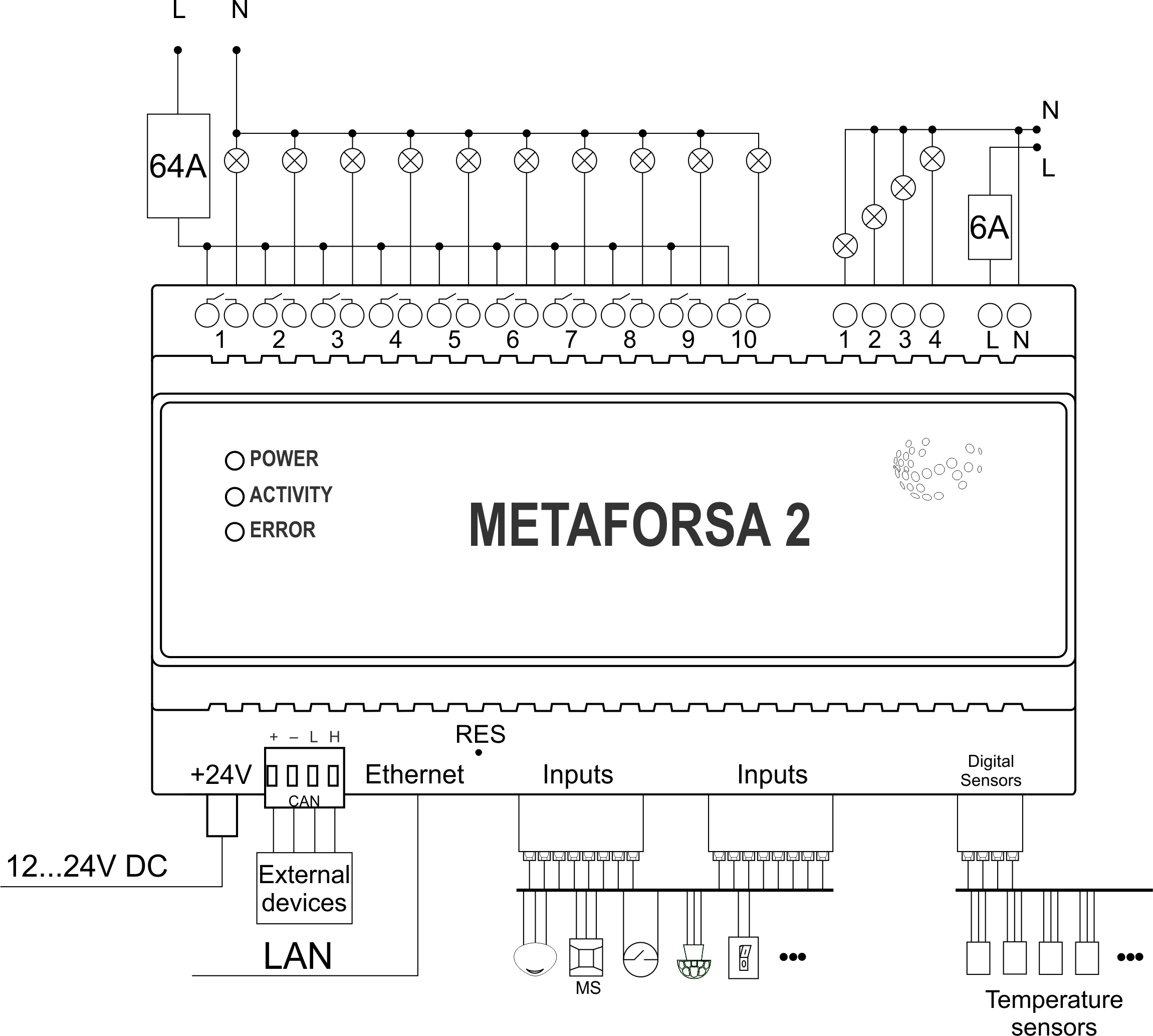
Typical diagram of METAFORSA MF-14.A module connection is shown in fig. 3.
Connection of the actuators
Connection of the lights/electric contactor/heating thermal actuator
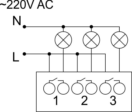 Fig. 4 |
Such actuators as light, electric contactor, heating thermal actuator should be switched on any of the outputs 1 – 10, the neutral wire and the ground wire should be connected directly to the switchboard. The example of connection is shown in Fig.4. |
Connection of high load device
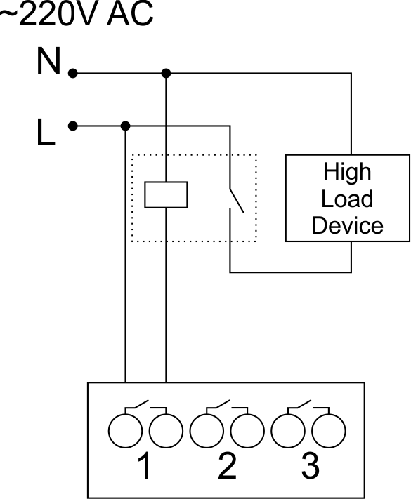 |
Recomended contactors:
|
Connection of single-pole water/gas supply valve
| Caution: Before applying power to the load, make sure that the output configuration of METAFORSA module is correct. The incorrect configuration or incorrect connection can cause the module failure and/or failure of the equipment connected to it, and even a fire. | |
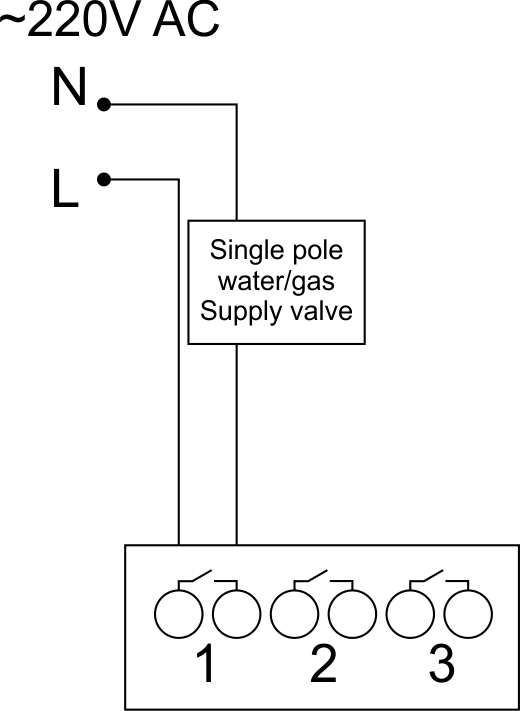 Fig. 5 |
The single pole water/gas supply valve is connected to any of the outputs of 1 – 10, the (neutral wire and the ground wire are connected directly to the switchboard. The example of connection is shown in Fig.5. |
Connection of double-pole water/gas supply valve
| Caution: Before applying power to the valve, it is necessary to ensure the output configuration of METAFORSA module is correct. The incorrect configuration can cause the voltage application simultaneously to both channels of the valve, which may result in the module failure and/or failure of the equipment connected to it, and even a fire. | |
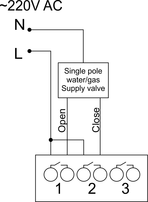 Fig. 6 |
Two adjacent contact points (for example, 3, 4) are used to connect the double-pole water/gas supply valve; in these conditions the neutral wire and the ground wire are connected directly to the switchboard. The example of connection is shown in Fig.6. |
Connection of single-pole gate actuator
| Caution: Before applying power to the module, you should properly configure access to the application. The contacts incorrectly configured can result in the module failure and/or failure of the equipment connected to it, and even a fire.
| |
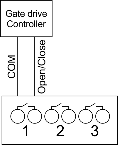 Fig. 7 |
Any contact point (for example, 3) is used to connect the single-pole gate drive controllers. The example of connection is shown in Fig.7. |
Connection of double-pole gate actuator
| Caution: Before applying power to the module, you must properly configure the outputs in the application. The contacts configured incorrectly can lead to simultaneous power supply to both channels, resulting in the module failure and/or failure of the equipment connected to it, and even a fire.
| |
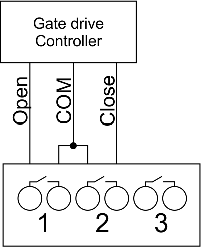 Fig. 8 |
Two adjacent contact points (for example, 3, 4) should be used to connect the double-pole gate drive controller. The example of connection is shown in Fig.8. |
Connection of curtain/jalousie/shutter actuator with 220V force control
| Caution: Before applying power to the module, you must properly configure the outputs in the application. The contacts configured incorrectly can lead to simultaneous power supply to both channels, resulting in the module failure and/or failure of the equipment connected to it, and even a fire.
| |
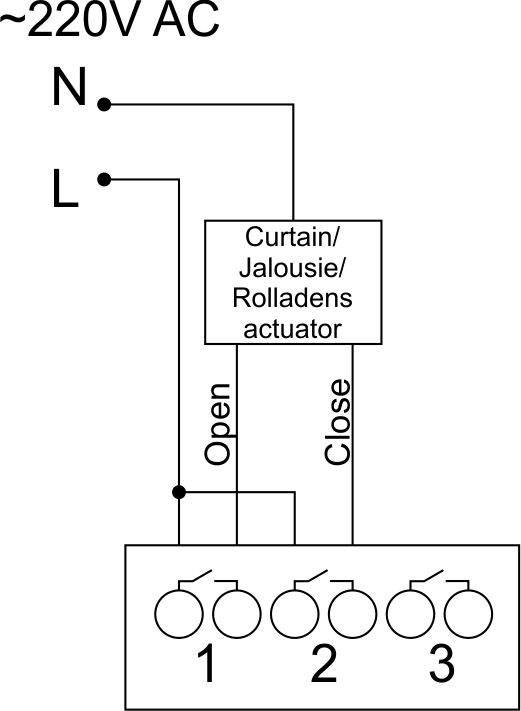 Fig. 9 |
Two adjacent contact points (for example, 3, 4) should be used to connect the curtain/jalousie/rolladens actuator, in these conditions the neutral wire and the ground wire are connected directly to the switchboard. The example of connection is shown in Fig.9. |
Connection of curtain/jalousie/shutter actuator with low-voltage control
| Caution: Before applying power to the module, you must properly configure the outputs in the application. The contacts configured incorrectly can lead to simultaneous power supply to both channels, resulting in the module failure and/or failure of the equipment connected to it, and even a fire.
| |
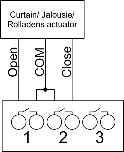 Fig. 10 |
Two adjacent contact points (for example, 3, 4) should be used to connect the curtain/jalousie/rolladens actuator with low-voltage control. The example of connection is shown in Fig.10. |
Connection of sensing elements/switches/buttons
Connection of motion sensors
The motion sensors should be connected to any free input in1-in24; in these conditions their power is connected to the contact points of +12V and GND of the relevant group. The example of connection is shown in Fig.11.
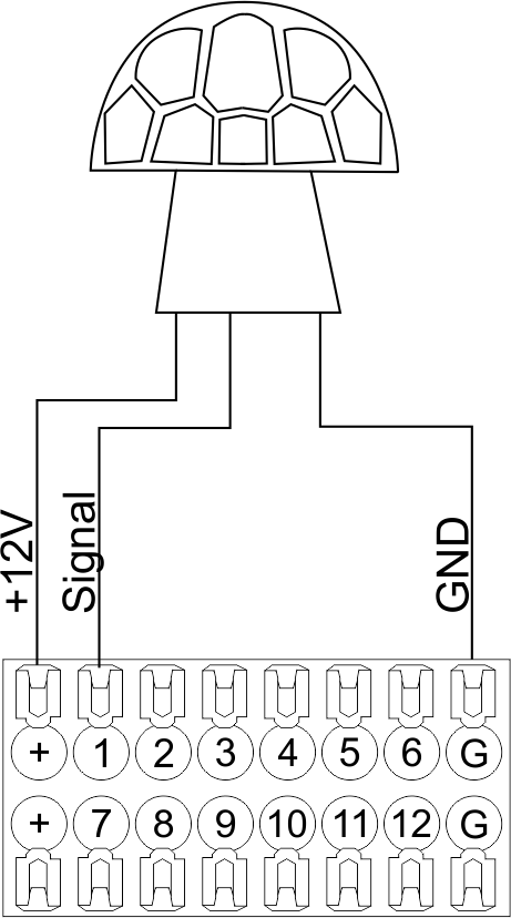
Fig. 11
Connection of FW-WL.A leakage sensors
FW-WL.A leakage sensors are connected to any free input in1 – in24, in these conditions the power should be connected to +12V and GND points of the relevant group. The example of connection is shown in fig. 12.
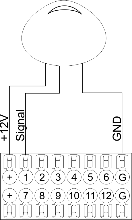 Fig12 |
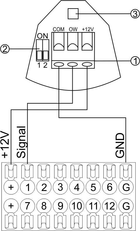 Fig13 |
Configuration and connection of the FW-WL.A sensor 1. Terminals:
- +12V — sensor power is connected to the contact point of METAFORSA “+12V”;
- OW — sensor pickup signal;
- GND — common, connected to GND contact of METAFORSA.
2. Sensor preset switch (optionally):
- 1 — sensor sensitivity (ON – high, OFF – low);
- 2 — indicator colour setting (ON – blue, OFF – green).
3. LED status indicator.
Connection of buttons/switches/magnetic reed switches
Buttons and reed switches are connected to any free input in1-in24, while their second contact point is connected to GND point of the relevant METAFORSA module group, + 12V power outputs – not in use. The example of connection is shown in Fig. 14-15.
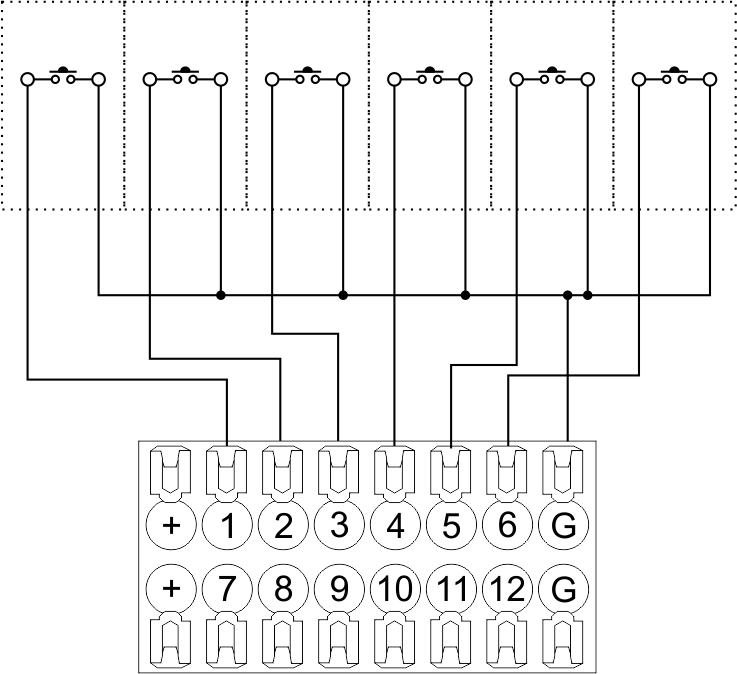 Fig14 connection of buttons/switching units |
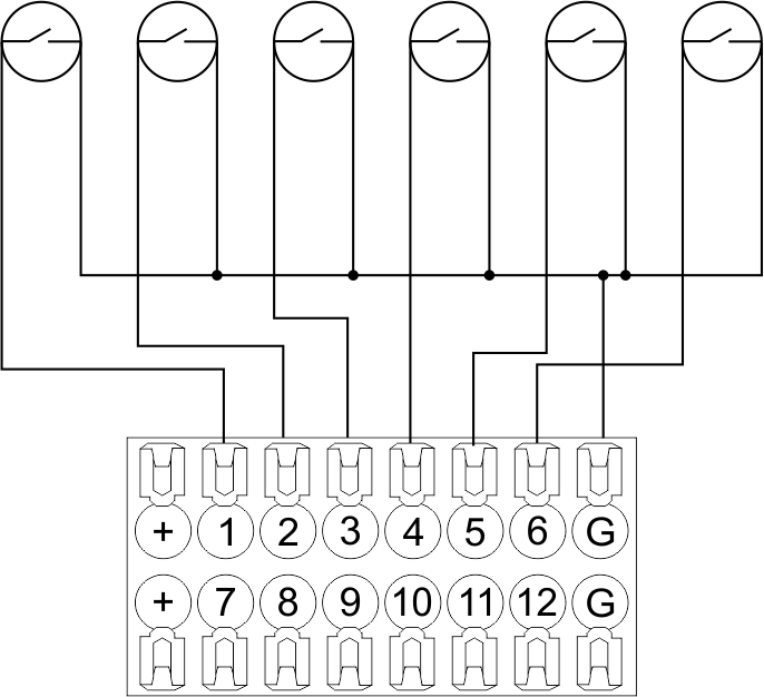 Fig15 connection of the magnetic reed switches (window/door position sensors) |
Connection of digital sensors
The OW adapter (Fig. 16a) is supplied along with METAFORSA module with the possibility to connect up to 8 digital sensors to it. In these conditions, several devices can be connected to one channel (Fig. 16b). The connected sensors are detected automatically and do not require any original setting.
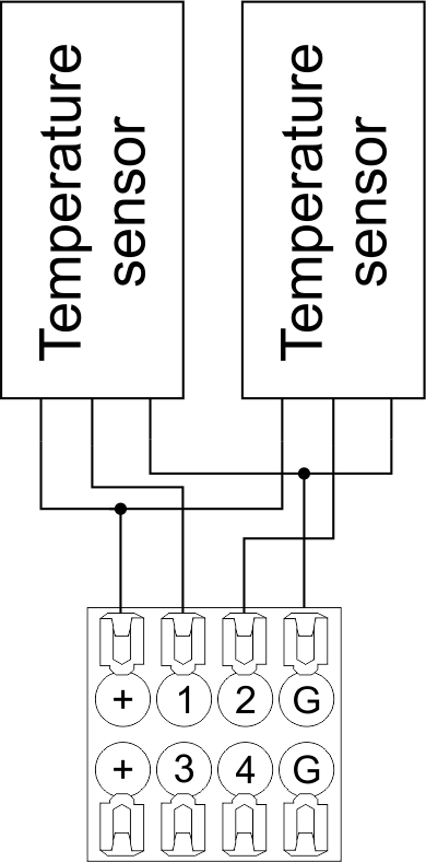 Fig16 a |
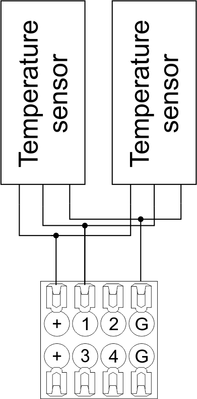 Fig16 b |
Configuration and connection of the OW adapter
Connection of auxiliary equipment.
Expansion modules include Larnitech equipment connected through the CAN-bus. Such equipment includes: dimmers, RGB-backlit control modules, multimode sensors, etc. The equipment connected to the expansion port is defined automatically and does not require any preset tuning. Connector contact pin assignment is defined in Table 4. The example of connection is shown in Fig. 17.

|
| Caution! The 120 ohm terminating resistors should be installed at the end connectors between L and H contact points of CAN-bus. Ensure the connection is correct. The incorrect connection may cause sensor and/or module malfunction. |
Module installation and connection procedure
- Install the module in the switchboard on the DIN-rail and fix it with the special latch on the module base.
- Fasten the supply unit on the left side of the module.
- Connect the connector (4) having the noise filter pre-installed which is supplied complete with the module.
- Connect the connectors (5), (6).
- Connect the connectors (1), (2).
- Connect the connector (3).
- Apply power to the supply unit of METAFORSA module.
- Wait until the module is loaded, then configure it in accordance with the System Setup Instructions.
- Apply power to the connectors (1), (2).
- Check all equipment for proper operation.
METAFORSA module shut-off and deinstallation procedure
- De-energize the module by disconnecting the circuit breaker assembly of the load power supply and METAFORSA module supply unit. Verify the voltage is absent on the terminals (1), (2) of the connector wires and on the input terminals of the supply unit.
- Disconnect the load power supply connectors (1), (2).
- Disconnect the connector (3).
- Disconnect the connectors (4)-(6).
- Remove the module from the DIN-rail, releasing the latch at the bottom of the module base.
Hardware setup
To configure and control METAFORSA SMART HOUSE, you must install Larnitech software on your smartphone or tablet, which is available in App Store and Play Market. After installation, follow the System Setup Instructions.
Fault diagnostics and handling
The following are some possible faults and ways of fault handling. If you have any difficulty, or face the fault undeclared here, please contact the Technical Support: [1] or [support@larnitech.com]. There are also some tips in the FAQ section at our website [2].
The actuators do not operate:
- ensure the outputs are properly configured in the application (see System Setup Instructions);
- check the connection is correct in accordance with table 2 and paragraph 3.6;
- ensure the power is supplied to the input power contact , i.e. all circuit breaker assembly are ON.
- verify the operability of the connected equipment.
The module is off, indication absent:
- check the connection to 24V supply unit as shown in table 2 (contacts pin assignment);
- check the connection of the supply unit to 220V power mains, the indicator should be ON.
Network connection fault:
- ensure the Ethernet cable is properly wired and connected to the connector;
- ensure the LED status indicators are ON on the Ethernet connector;
- check the LAN configuration is correct, Ethernet cable loops are absent;
- METAFORSA module and the device you are connecting from are in the same network.
hold integer 0-10000 1-10 by default hold is the same as runtime hold is the bridging time in miliseconds, is used for gate and jalousie, lock; Example: hold=3500
The sensors do not operate:
- ensure the inputs are properly configured in the application (System Setup Instructions);
- check the connection is correct in accordance with table 2 and paragraph 3.7;
- ensure the METAFORSA module is ON: circuit breaker assembly is closed, indication on the supply unit is ON, the module indication corresponds to the operating status – table 3;
- check the power supply availability on the sensors;
- check the integrity of lines laid to the sensors.
The auxiliary equipment does not operate:
- check the connection is correct in accordance with table 2 and paragraph 3.8-9;
- ensure the METAFORSA module is ON: circuit breaker assembly is closed, indication on the supply unit is ON, the module indication corresponds to the operating status – table 3;
- check the integrity of the CAN lines, voltage supply on the modules.
HW Settings
| Name | Type, range | SUBID | Default | Description |
|---|---|---|---|---|
| runtime | integer 0-100 | 1-10 | 15 | runtime is the open/close time in seconds, is used for jalousie, gate, valve(2 pole);
|
| runtimeopen | integer 0-60000 | Blinds subId | Runtimeopen is the open time in milliseconds, is used for blinds; Example: runtimeopen=15000 | |
| runtimeclose | integer 0-60000 | Blinds subId | Runtimeclose is the close time in milliseconds, is used for blinds; Example: runtimeclose=15000 | |
| hold | integer 0-10000 | 1-10 | 500 | hold is the bridging time in milliseconds, is used for gate and jalousie (by default hold is the same as runtime for jalousie and gate), lock; Example: hold=3500 |
| def | string 'ON' | 1-10 | 'OFF' | def is the element status is set after restart, is used for lamp, heating, valve(1 pole); Example: def='ON' |
| stop | Char ‘R’ | 1-7 | – | (for 2-pole gate and blinds) If it is declared then by Stop command during the motion, the same impulse appears as it was at the beginning of the motion. Pole, an which the stop-impules is formed, is defined by the parameter Stop value. If it is ‘r’ or ‘R’ then stop-impulse is produced on the opposite to the start-impulse pole. If any other value is delcared (e.g., ‘d’ ) then the stop-impulse is on the same pole. If a Runtime passed after the beginning of the motion then the stop-impulse is not formed. Example: stop=’r’ |
| out | char[10] | 98 | 'LLLLHHHHP-' | Each char is responsible for the type of a particular channel
Example: out='LLB-G-V-W-' |
| dm | char[4] | 98 | ‘LLLL’ | Each char is responsible for the type of a particular channel
Example: dm=’skl-‘ |
| def | integer 0-250 | 11-14 | 100 | The default brightness level in case of a power reset (1..250). Example: def=250 |
| min | integer 0-100 | 11-14 | 0 | Minimum dimming level, example: min=10 |
| max | integer 0-100 | 11-14 | 100 | Maximum dimming level, example max=95 |
| start | integer 0-100 | 11-14 | 0 | The Start function is used for lamps that lack the minimal voltage to get turned on. If the set value is lower than the start value, the lamp is turned on at the start value and them the light is dimmed down to the set level. Example: start=60 |
| force | integer 0-100 | 11-14 | 10 | Time duration of the starting value (measured in milliseconds). Example: force=20 |
| runtime | integer 0-60000 | 11-14 | 1000 | Runtime is the speed of changing the brightness from ‘min’ to ‘max’ (measured in milliseconds). Example: runtime=1000 |
| offset | integer (+/- 0…39) | 39-46 | '0' | sensor values offset; For example, offset is -3.8 :
Example: hw="offset='-3.8'" |
| in | char[24] | 98 | 'BBBBBBBBBBBBMMMLLLKKKKKK' | Each char is responsible for the type of a particular channel
Example: in='MMMMMMMMMMMMLLLLLLLLLLLL' 12 motion sensors and 12 leak-sensors; in='BBBBBBBBSSSSSSBBBBSSSSSS' 12 buttons; 12 switches. |
 1<item addr="339:1" auto-period="600" cfgid="40" hw="def='ON'" name="Lamp" type="lamp" uniq_id="3779">
 2<item addr="339:2" cfgid="40" hw="def='ON'" name="Radiator" type="valve-heating" uniq_id="3780">
 3    <automation name="Eco" temperature-level="16" uniq_id="3781"/>
 4    <automation name="Comfort" temperature-level="22" uniq_id="3782"/>
 5    <automation name="Hot" temperature-level="25" uniq_id="3783"/>
 6</item>
 7<item addr="339:3" cfgid="40" hw="runtime=9" name="Jalousie" sub-type="120" type="jalousie" uniq_id="32"/>
 8<item addr="339:5" cfgid="40" hw="runtime=13" name="Gate" sub-type="120" type="gate" uniq_id="3784"/>
 9<item addr="339:7" cfgid="40" hw="hold=4600" name="Gate" sub-type="120" type="gate" uniq_id="3785"/>
10<item addr="339:8" cfgid="40" hw="runtime=10" name="Valve" type="valve" uniq_id="3786"/>
11<item addr="339:11" cfgid="40" name="Motion" type="motion-sensor" uniq_id="17"/>
12<item addr="339:12" cfgid="40" name="Motion" type="motion-sensor" uniq_id="18"/>
13<item addr="339:13" cfgid="40" name="Motion" type="motion-sensor" uniq_id="19"/>
14<item addr="339:16" cfgid="40" name="Leak" type="leak-sensor" uniq_id="21"/>
15<item addr="339:17" cfgid="40" name="Leak" type="leak-sensor" uniq_id="41"/>
16<item addr="339:19" cfgid="40" name="Switch" type="switch" uniq_id="22"/>
17<item addr="339:20" cfgid="40" name="Switch" type="switch" uniq_id="23"/>
18<item addr="339:21" cfgid="40" name="Switch" type="switch" uniq_id="24"/>
19<item addr="339:22" cfgid="40" name="Switch" type="switch" uniq_id="25"/>
20<item addr="339:23" cfgid="40" name="Door" type="door-sensor" uniq_id="26"/>
21<item addr="339:24" cfgid="40" name="Door" type="door-sensor" uniq_id="27"/>
22<item addr="339:25" cfgid="40" name="Door" type="door-sensor" uniq_id="28"/>
23<item addr="339:26" cfgid="40" name="Door" type="door-sensor" uniq_id="29"/>
24<item addr="339:30" cfgid="40" name="Temperature" type="temperature-sensor" uniq_id="3772"/>
25<item addr="339:31" cfgid="40" name="Temperature" type="temperature-sensor" uniq_id="3773"/>
26<item addr="339:32" cfgid="40" name="Temperature" type="temperature-sensor" uniq_id="3774"/>
27<item addr="339:33" cfgid="40" hw="offset='-10.8'" name="Temperature" type="temperature-sensor" uniq_id="3775"/>
28<item addr="339:34" cfgid="40" hw="offset='25.1'" name="Temperature" type="temperature-sensor" uniq_id="3776"/>
29<item addr="339:35" cfgid="40" name="Temperature" type="temperature-sensor" uniq_id="3777"/>
30<item addr="339:36" cfgid="40" name="Temperature" type="temperature-sensor" uniq_id="3778"/>
31<item addr="339:98" cfgid="40" hw="out='LHB-G-XV--' in='MMM--LL-BBBBKKKK'" name="Temperature" system="yes" type="temperature-sensor" uniq_id="30"/>