Difference between revisions of "Metaforsa2 MF-14/nl"
(Created page with "{| class="wikitable" style="width:800px"; |- |colspan="2" style="background-color:#dededf" |'''Let op: Voordat u de belasting van stroom voorziet, moet u ervoor zorgen dat de...") Tags: Mobile web edit Mobile edit |
(Created page with "====Aansluiting van dubbelpolige water-/gastoevoerklep====") Tags: Mobile web edit Mobile edit |
||
| Line 357: | Line 357: | ||
| − | ==== | + | ====Aansluiting van dubbelpolige water-/gastoevoerklep==== |
{| class="wikitable" style="width:800px"; | {| class="wikitable" style="width:800px"; | ||
Revision as of 15:54, 12 March 2024
| MF-14 | |||||||||||||
|---|---|---|---|---|---|---|---|---|---|---|---|---|---|
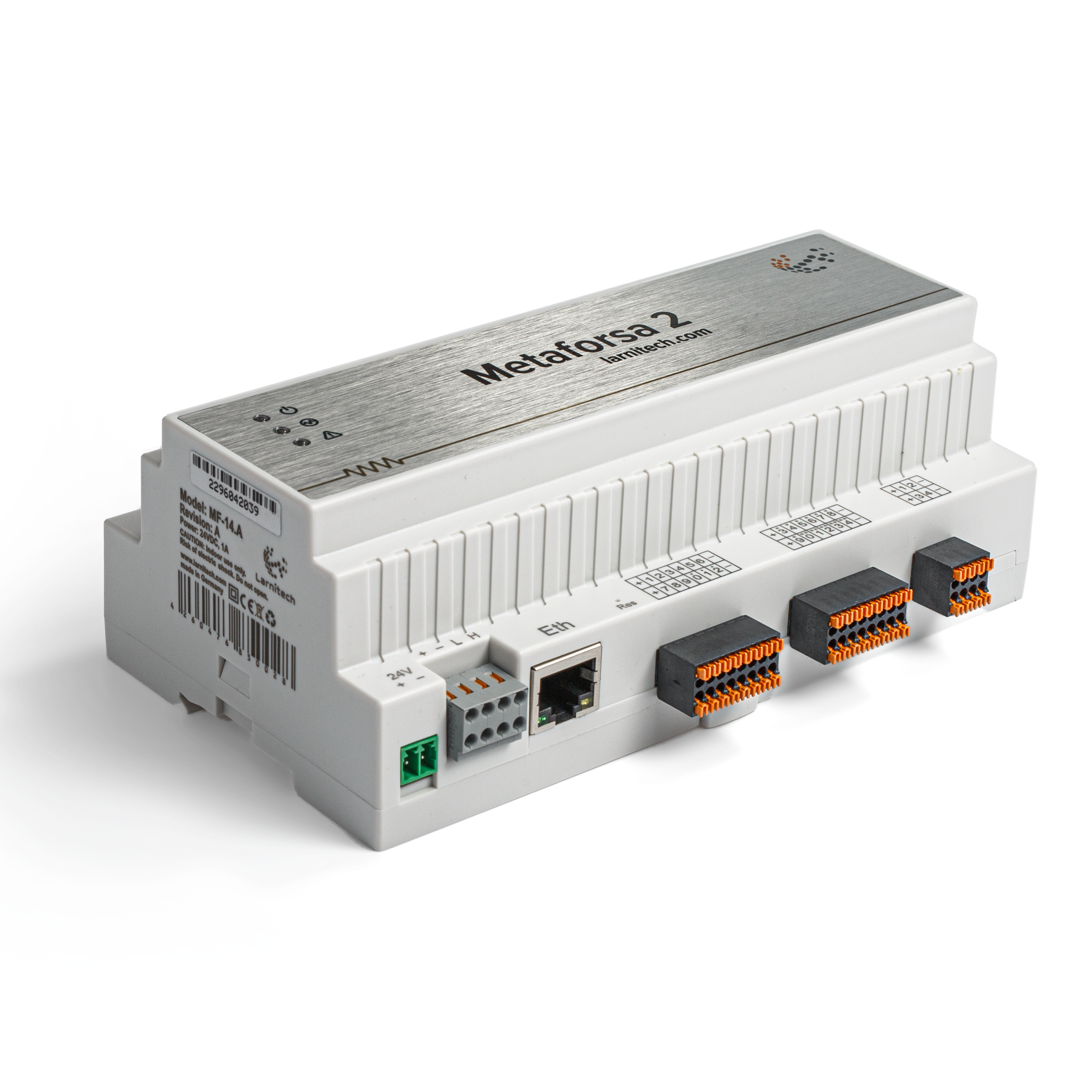 | |||||||||||||
| |||||||||||||
| |||||||||||||
| |||||||||||||
Introductie
METAFORSA SMART HOUSE Installatiehandleiding beschrijft de procedure voor de installatie, montage, bediening en instelling. Tijdens het werken met het systeem dient u zich strikt te houden aan alle eisen die in deze handleiding worden gesteld. Het niet naleven ervan kan leiden tot schade aan het apparaat, defecten ervan, elektrische schokken, brand en andere gevolgen. De fabrikant behoudt zich het recht voor om zonder voorafgaande kennisgeving wijzigingen in deze handleiding aan te brengen. Deze handleiding is een integraal onderdeel van het systeem en blijft bij de eindgebruiker.
Kenmerken
- 10 universele uitgangen ondersteunen:
- Lichten
- NC/NO verwarmingskleppen
- Jaloezieën
- 1- of 2-polige poorten
- 1- of 2-polige kranen
- NC/NO-sloten
- Ventilatorconvectoren
- 4 dimuitgangen
- 24 Discrete ingangen die ondersteunen:
- Toetsen
- Schakelaars
- reedschakelaars
- leksensoren
- bewegingsmelders
- 4 digitale ingangen voor maximaal 8 temperatuursensoren
- Uitbreidingspoort
- Relais met AgSnO2-contacten geschikt voor een inschakelstroom van 80A en 20 ms
- Cloudverbinding en controle van alle huissystemen
- Stembediening (Siri, Alexa, Google Home)
- Plugins-engine maakt uitbreiding van de systeemmogelijkheden mogelijk (bijvoorbeeld integratie met Satel, Philips Hue, IKEA-lampen)
- Veiligheid tegen ongeoorloofde inbraak verzekerd met RSA/AES256-codering
- Push notificaties van het systeem op je telefoon (ook mogelijk te ontvangen via Telegram en Viber messengers)
- Geschiedenis (metergegevens voor 1 jaar worden opgeslagen)
- Plug and play (mogelijkheid tot snelle en gebruiksvriendelijke uitbreiding van het systeem)
- Regelmatige systeemupdates
- Grote, voortdurend bijgewerkte database met scripts om aan al uw behoeften te voldoen
- Automatische dagelijkse back-ups via de cloud met de mogelijkheid om de initiële configuratie te herstellen
- Open API (waarmee Larnitech in andere systemen kan worden geïntegreerd)
- Interactieve en gebruiksvriendelijke LT SETUP-webinterface beschikbaar voor geavanceerde configuratie
- Plug-and-play
- Het is een volledig kant-en-klare Smart Home-systeemkit
Veiligheidseisen
Om het risico op brand, elektrische schokken, schade aan het systeem en/of persoonlijk letsel te voorkomen, moet de installatie en montage van het systeem worden uitgevoerd in overeenstemming met de onderstaande instructies:
- alle aansluitwerkzaamheden moeten zonder stroom worden uitgevoerd;
- gebruik geschikt gereedschap en persoonlijke bescherming tegen elektrische schokken;
- gebruik geen beschadigde kabels, draden en connectoren;
- vermijd het opvouwen van kabels en draden;
- Knijp of knik de kabels en draden niet door overmatige kracht uit te oefenen. Anders kunnen de binnenste geleiders van de kabel en draden worden gestript of kapot gaan;
- Gebruik geen stopcontact met slechte contacten om verbinding te maken;
- overschrijd de in deze handleiding gespecificeerde limiet voor de belastingsparameters niet;
- de draaddoorsnede van de voedingsgeleiders is onderworpen aan de specificaties voor de stroomdichtheidslimiet, het isolatietype en het draadmateriaal. Lichtdoorsnede kan leiden tot oververhitting van de kabel en brand.
Bij werkzaamheden met het systeem na spanningstoevoer NOOIT:
- aansluiten/loskoppelen van connectoren;
- open modules en sensoren.
Systeemconfiguratie en doel
Doel van het systeem
METAFORSA SMART HOUSE is een kant-en-klare oplossing voor de automatisering van residentiële en commerciële gebouwen en hotelcomplexen die de meest gewenste kenmerken van Smart House omvat.
Het apparaat heeft 10 besturingskanalen, 4 dimkanalen, 24 inkomende sensorkanalen en een aansluitpoort voor digitale sensoren.
| Universele uitgangen kunnen worden gebruikt voor het aansturen van: | Met universele ingangen kunt u verbinding maken met: |
|---|---|
| Verlichting | Knoppen/schakeleenheden |
| Stekkerconnectoren | Magnetische reedschakelaars |
| Vloerverwarming | Bewegingssensoren |
| Gordijn-/poortactuatoren | Lekkage sensoren |
| Kleppen watertoevoer/verwarming |
Aansluitpoort digitale sensoren
Met de verbindingspoort voor digitale sensoren kunt u een verscheidenheid aan digitale sensoren aansluiten, zoals temperatuursensoren, omgevingslicht, vochtigheid en andere.
Uitbreidingspoort
Met de uitbreidingspoort kunt u het systeem upgraden door hulpapparatuur aan te sluiten, zoals de besturingsmodule voor LED-verlichting, dimmen, meetapparatuur en andere elementen.
Het pakket, dat volledig installatieklaar is, omvat de basishardware en -software.
Inhoud pakket
Het pakket wordt standaard geleverd met:
| Hoofdframe METAFORSA MF-14.А | 1 st |
| Voedingseenheid MEANWELL DR-15-12 | 1 st |
| Bewegingssensor CW-MSD | 3 stuks |
| Lekkagesensor FW-WL.A | 2 stuks |
| Temperatuurgevoelig element FW-TS.A | 4 stuks |
| Magnetische reedschakelaar (raam-/deurpositiesensor) | 4 stuks |
| Ethernet-kabelruisfilter | 1 st |
| Netsnoer | 1 st |
Technische basisspecificaties van het systeem
De basisspecificaties en kenmerken van de module METAFORSA MF-14.A zijn weergegeven in tabel 1
| Specificatie | Betekenis |
|---|---|
| Uitgangspoorten | |
| Aantal geschakelde kanalen | 10 |
| Aantal geschakelde groepen | 10 |
| Aantal dimkanalen | 4 |
| Commutatiespanning | 0-250 V AC/DC |
| Piekbelasting (één kanaal) | 16A |
| Piekbelasting (apparaat) | 160A |
| Max. belasting per dimkanaal | 0,5A (110W bij 220V) |
| Dimmertype | MOSFET |
| Type dimmerbelasting | R,C |
| Dimtype | achterrand |
| Type aansluiting voedingskabel | aansluiting |
| Toegestane doorsnede van de voedingskabel voor aansluiting op stopcontact: enkeladerige kabel meeraderige kabel meeraderige kabel met punt |
0,5 … 4 mm2 0,5 … 4 mm2 0,5 … 2,5 mm2 |
| Invoerpoorten | |
| Aantal discrete ingangen | 24 |
| Aantal digitale ingangen | 4 |
| Maximale stroomsterkte op de gelijkstroomspanningsconnectoren | 50mA |
| Anders | |
| Bedrijfstemperatuur | 0 … +45°С |
| Opslag-/transporttemperatuur | -20 … +60°С |
| Toegestane vochtigheid | 0 … 95% (niet-condenserend) |
| Voeding | 12 … 27,5 V DC 24 V, 0,75 A Aanbevolen |
| Maximale vraag | 0,5А |
| Beschikbare interfaces | Ethernet, KAN, OneWire |
| Bustype | CAN (4-draads) |
| KAN (4-draads) | 800 m* (twisted pair 5 cat) |
| CAN-draadtype | FTP-Cat 5E |
| CAN-verbindingstype | aansluiting |
| Maximale lengte digitale lijn | 30 m |
| Digitaal lijnbedradingstype | UTP/FTP Cat 5E |
| LAN maximale lengte | 100 m |
| LAN-draadtype | UTP/FTP Cat 5E |
| LAN-verbindingstype | Connector RJ-45 |
| Dimensionale specificaties | 9U, 156x110x58 mm |
| Schelpmateriaal | ABS-kunststof |
| Behuizing | IP40 |
| Installatietype apparatuur | DIN-rail (EN 60715) |
| Gewicht | 400 gr |
* – het installeren van extra voedingseenheden is vereist voor lange lijnen; de maximale lengte van de lijn kan worden verminderd door verschillende interferentiefactoren
Algemene structuur van het systeem
Het algemene overzicht van de module wordt getoond in fig. 1
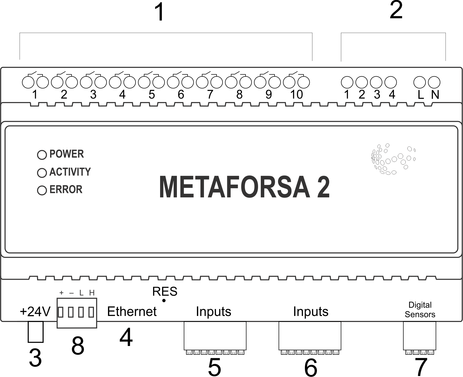
| 1 | — connector voor belastingstoepassing |
| 2 | — connector voor toepassing van dimlampen |
| 3 | - stekker |
| 4 | — Ethernet-netwerkconnector |
| 5-6 | — connectoren voor digitale sensoren en knoppen/schakeleenheden |
| 7 | — OneWire-interfaceconnector (voor digitale sensoren) |
| 8 | — connector voor uitbreidingsmodule. |
Overzicht van de externe connectoren van het METAFORSA-apparaat:
Bovenaan de behuizing (fig. 1) bevindt zich:
- connector (1) — Apparatenaansluiting;
- connector (2) — Aansluiting lampen dimmen;
Onderaan de behuizing (fig. 1) bevindt zich:
- connector (3) — aansluiting voor modulevoeding;
- connector (4) — Ethernet-netwerkverbinding;
- connectoren (5-6) — vier zespuntsconnectoren voor aansluiting van digitale sensoren – bewegings-, lekkage-, reedschakelaarsensoren en *knop-/schakeleenheidsensoren;
- connector (7) — Busverbinding met OneWire digitale sensoren;
- connector (8) — aansluiting uitbreidingsmodule.
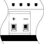
De fysieke configuratie en contactpunttoewijzing van elke connector worden weergegeven in tabel 2.
| Connector | Contact | Toewijzing |
|---|---|---|
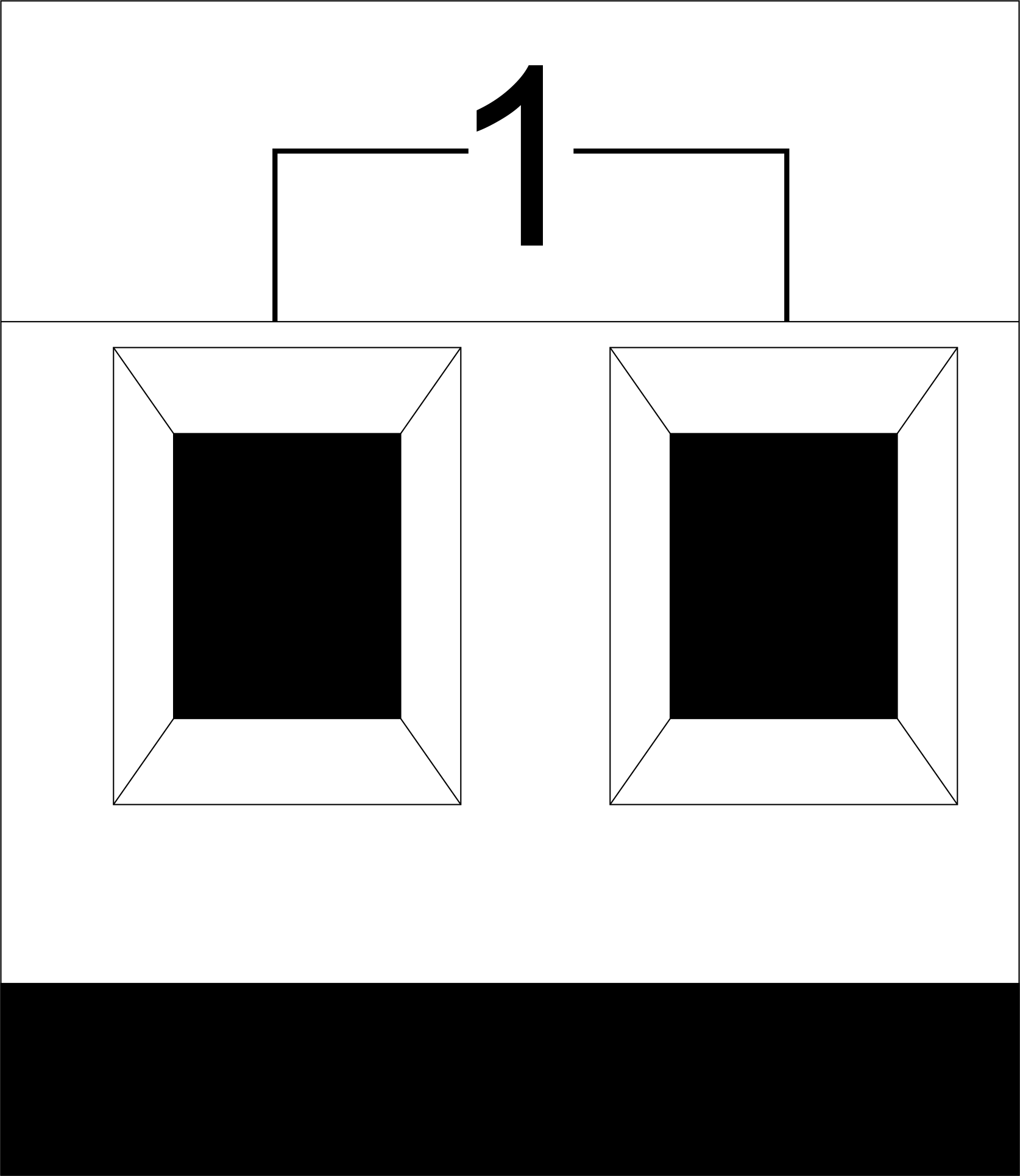 |
1-10 | Belastingstoepassing (lichtlampen, thermische actuatoren, enz.) |
| D1-4, L, N | Belastingtoepassing (lampen dimmen) | |
| Apparaatstatusindicatoren | De modulestatusindicatoren worden beschreven in tabel 3 | |
 |
+24V GND |
+24V — modulevoeding door een externe 24 V-voeding GND — gemeenschappelijk |
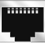 |
RJ45 | Connector voor LAN-connectiviteit |
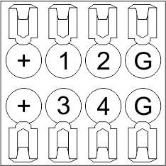
| In1-12, In13-24 GND | Aansluiting van besturingsapparaten (knoppen, magnetische reedschakelaars, bewegings- of lekkagesensoren): +12V — uitgangsvermogen sensor +12 V In1 … In24 — logische ingangen (0-12 V) GND — gemeenschappelijk | |
 |
OneWire | Aansluiting digitale sensoren (temperatuur) VCC — voedingsuitgang sensoren +5V OW1-OW4 — OneWire databussen GND — gemeenschappelijk |
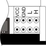 |
VCC GND L H |
Aansluiting externe modules voor CAN-bus VСС — 24V-uitgang voor voeding van externe apparaten GND — gemeenschappelijk L — CAN-L databus H — CAN-H databus |
| Indicator | Status | Description |
|---|---|---|
| Power | Power | |
| Power not available | ||
| Activity | Data communication | |
| Data communication not available | ||
| Error | No errors | |
| Communication error | ||
| Module overheat | ||
| Dimmer outputs module overload | ||
| Absence of power on dimmers, if in configuration |
Systeeminstallatie en montage
Voordat u het systeem aansluit, moet u:
- plaats de sensor en actuatoren (indien niet vooraf geïnstalleerd), stel de sensoren en actuatoren in;
- plaats de module en de voeding.
Opmerking: De module moet in de buurt van de voedingsspanningsbron worden geïnstalleerd.
- Het vermogen van de stroomonderbreker moet overeenkomen met het draagvermogen;
- Niets anders dan de fasegeleiders kunnen op de module worden aangesloten, de nuldraad wordt apart aangesloten.
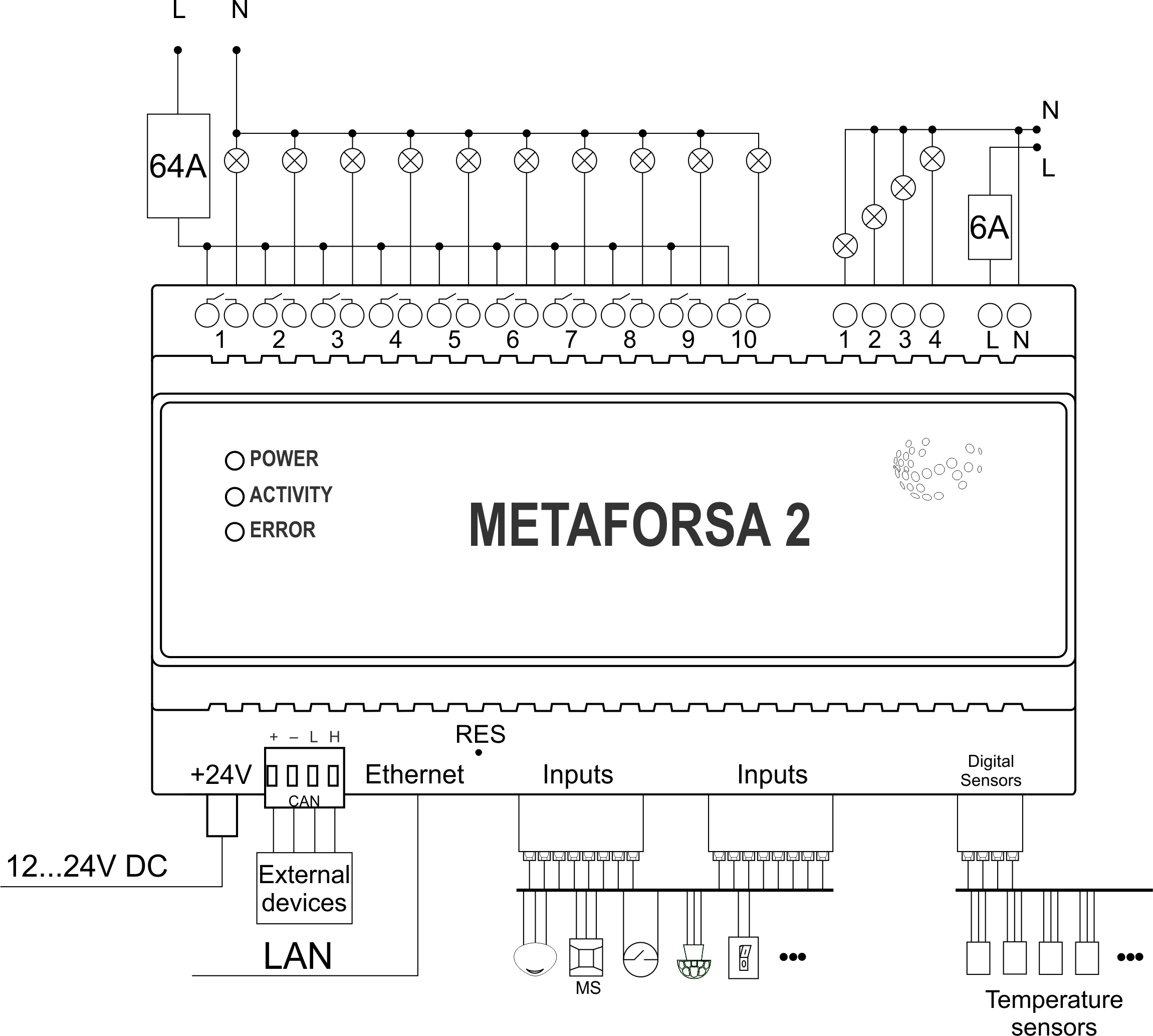
Een typisch diagram van METAFORSA MF-14.A moduleaansluiting wordt getoond in fig. 3.
Aansluiting van de aandrijvingen
Aansluiting van de verlichting/elektrische schakelaar/thermische actuator voor verwarming
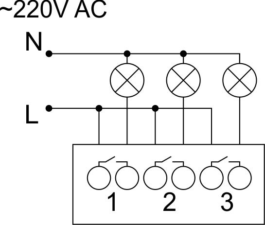 Fig. 4 |
Dergelijke actuatoren zoals licht, elektrische schakelaars en thermische thermische actuatoren moeten worden ingeschakeld op een van de uitgangen 1 – 10, de neutrale draad en de aardedraad moeten rechtstreeks op het schakelbord worden aangesloten. Het aansluitvoorbeeld wordt getoond in Fig. 4. |
Aansluiting van apparaat met hoge belasting
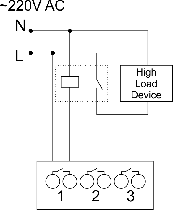 |
Aanbevolen schakelaars:
|
Aansluiting van eenpolige water-/gastoevoerklep
| Let op: Voordat u de belasting van stroom voorziet, moet u ervoor zorgen dat de uitgangsconfiguratie van de METAFORSA-module correct is. Een onjuiste configuratie of onjuiste aansluiting kan leiden tot het falen van de module en/of het falen van de daarop aangesloten apparatuur, en zelfs tot brand. | |
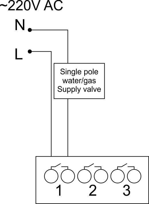 Fig. 5 |
De enkelpolige water-/gastoevoerklep wordt aangesloten op een van de uitgangen van 1 – 10, de neutrale draad en de aardedraad zijn rechtstreeks op het schakelbord aangesloten. Het aansluitvoorbeeld wordt getoond in Fig.5. |
Aansluiting van dubbelpolige water-/gastoevoerklep
| Caution: Before applying power to the valve, it is necessary to ensure the output configuration of METAFORSA module is correct. The incorrect configuration can cause the voltage application simultaneously to both channels of the valve, which may result in the module failure and/or failure of the equipment connected to it, and even a fire. | |
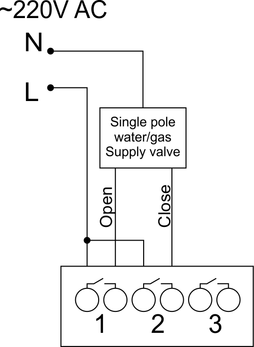 Fig. 6 |
Two adjacent contact points (for example, 3, 4) are used to connect the double-pole water/gas supply valve; in these conditions the neutral wire and the ground wire are connected directly to the switchboard. The example of connection is shown in Fig.6. |
Connection of single-pole gate actuator
| Caution: Before applying power to the module, you should properly configure access to the application. The contacts incorrectly configured can result in the module failure and/or failure of the equipment connected to it, and even a fire.
| |
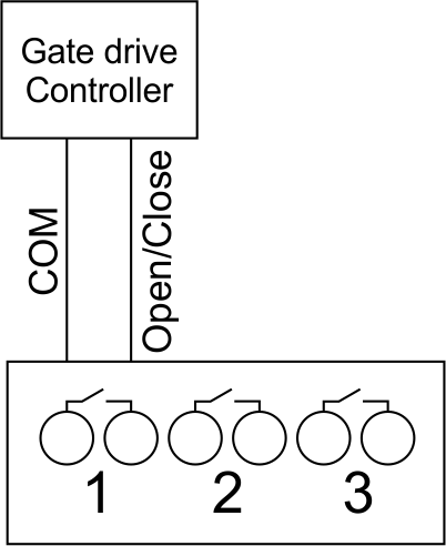 Fig. 7 |
Any contact point (for example, 3) is used to connect the single-pole gate drive controllers. The example of connection is shown in Fig.7. |
Connection of double-pole gate actuator
| Caution: Before applying power to the module, you must properly configure the outputs in the application. The contacts configured incorrectly can lead to simultaneous power supply to both channels, resulting in the module failure and/or failure of the equipment connected to it, and even a fire.
| |
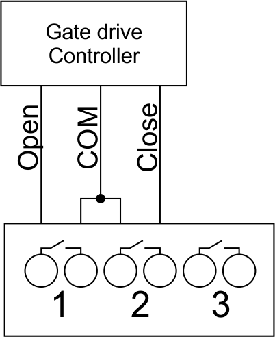 Fig. 8 |
Two adjacent contact points (for example, 3, 4) should be used to connect the double-pole gate drive controller. The example of connection is shown in Fig.8. |
Connection of curtain/jalousie/shutter actuator with 220V force control
| Caution: Before applying power to the module, you must properly configure the outputs in the application. The contacts configured incorrectly can lead to simultaneous power supply to both channels, resulting in the module failure and/or failure of the equipment connected to it, and even a fire.
| |
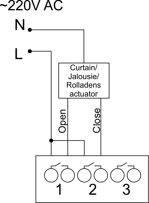 Fig. 9 |
Two adjacent contact points (for example, 3, 4) should be used to connect the curtain/jalousie/rolladens actuator, in these conditions the neutral wire and the ground wire are connected directly to the switchboard. The example of connection is shown in Fig.9. |
Connection of curtain/jalousie/shutter actuator with low-voltage control
| Caution: Before applying power to the module, you must properly configure the outputs in the application. The contacts configured incorrectly can lead to simultaneous power supply to both channels, resulting in the module failure and/or failure of the equipment connected to it, and even a fire.
| |
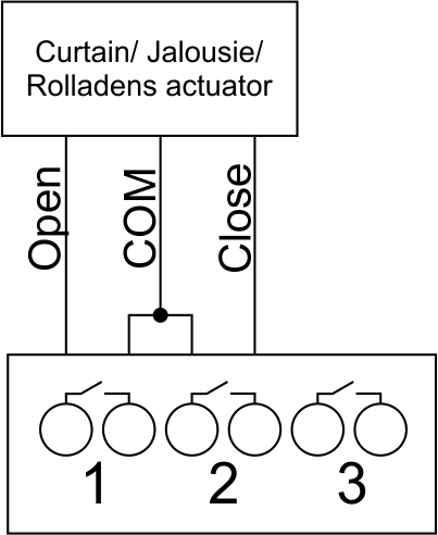 Fig. 10 |
Two adjacent contact points (for example, 3, 4) should be used to connect the curtain/jalousie/rolladens actuator with low-voltage control. The example of connection is shown in Fig.10. |
Connection of sensing elements/switches/buttons
Connection of motion sensors
The motion sensors should be connected to any free input in1-in24; in these conditions their power is connected to the contact points of +12V and GND of the relevant group. The example of connection is shown in Fig.11.
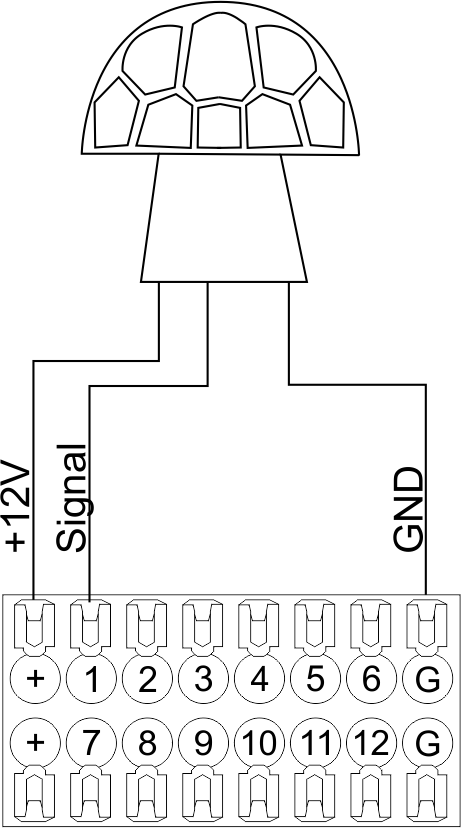
Fig. 11
Connection of FW-WL.A leakage sensors
FW-WL.A leakage sensors are connected to any free input in1 – in24, in these conditions the power should be connected to +12V and GND points of the relevant group. The example of connection is shown in fig. 12.
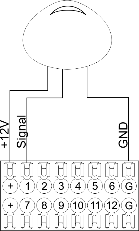 Fig12 |
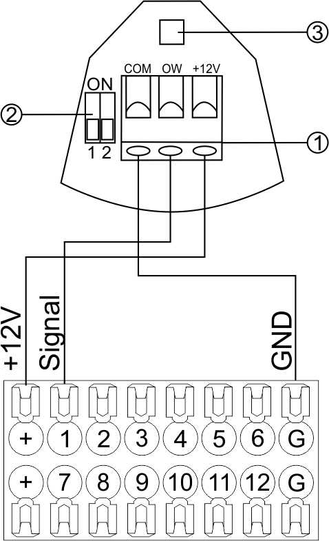 Fig13 |
Configuration and connection of the FW-WL.A sensor 1. Terminals:
- +12V — sensor power is connected to the contact point of METAFORSA “+12V”;
- OW — sensor pickup signal;
- GND — common, connected to GND contact of METAFORSA.
2. Sensor preset switch (optionally):
- 1 — sensor sensitivity (ON – high, OFF – low);
- 2 — indicator colour setting (ON – blue, OFF – green).
3. LED status indicator.
Connection of buttons/switches/magnetic reed switches
Buttons and reed switches are connected to any free input in1-in24, while their second contact point is connected to GND point of the relevant METAFORSA module group, + 12V power outputs – not in use. The example of connection is shown in Fig. 14-15.
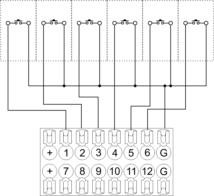 Fig14 connection of buttons/switching units |
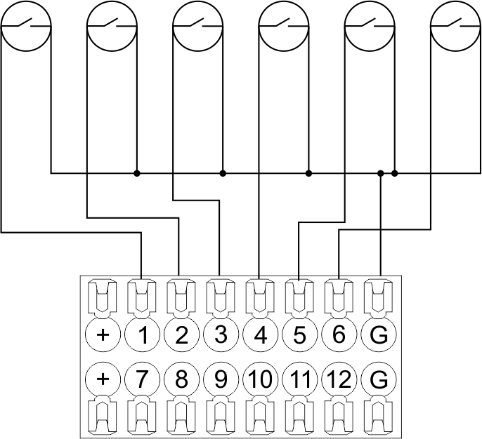 Fig15 connection of the magnetic reed switches (window/door position sensors) |
Connection of digital sensors
The OW adapter (Fig. 16a) is supplied along with METAFORSA module with the possibility to connect up to 8 digital sensors to it. In these conditions, several devices can be connected to one channel (Fig. 16b). The connected sensors are detected automatically and do not require any original setting.
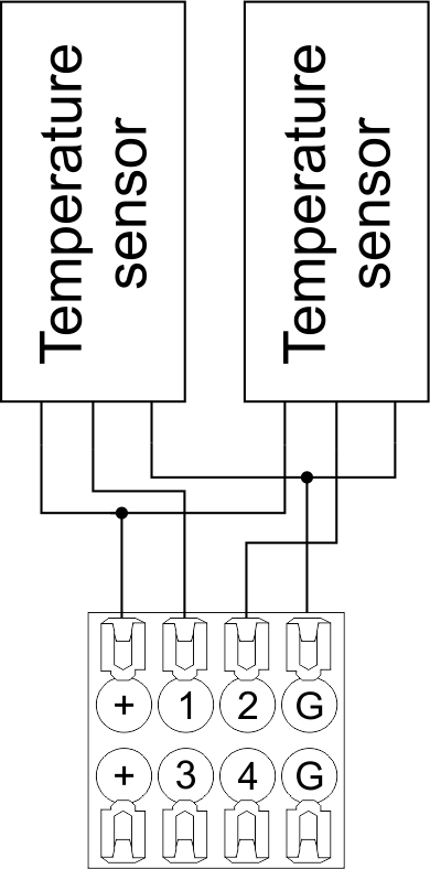 Fig16 a |
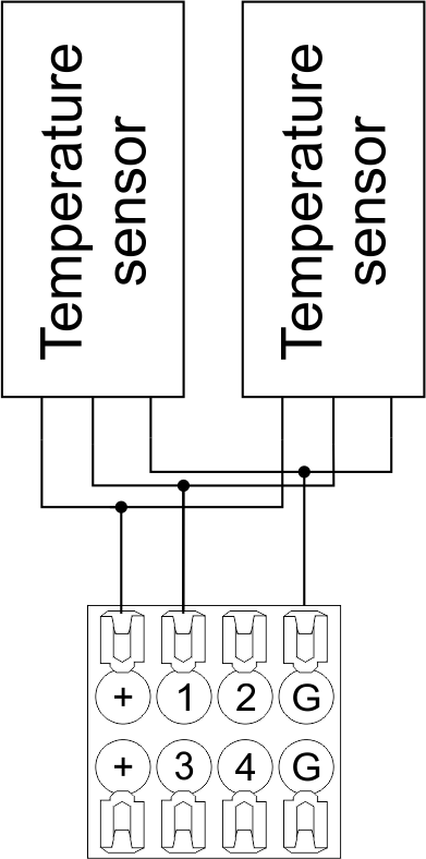 Fig16 b |
Configuration and connection of the OW adapter
Connection of auxiliary equipment.
Expansion modules include Larnitech equipment connected through the CAN-bus. Such equipment includes: dimmers, RGB-backlit control modules, multimode sensors, etc. The equipment connected to the expansion port is defined automatically and does not require any preset tuning. Connector contact pin assignment is defined in Table 4. The example of connection is shown in Fig. 17.

|
| Caution! The 120 ohm terminating resistors should be installed at the end connectors between L and H contact points of CAN-bus. Ensure the connection is correct. The incorrect connection may cause sensor and/or module malfunction. |
Module installation and connection procedure
- Install the module in the switchboard on the DIN-rail and fix it with the special latch on the module base.
- Fasten the supply unit on the left side of the module.
- Connect the connector (4) having the noise filter pre-installed which is supplied complete with the module.
- Connect the connectors (5), (6).
- Connect the connectors (1), (2).
- Connect the connector (3).
- Apply power to the supply unit of METAFORSA module.
- Wait until the module is loaded, then configure it in accordance with the System Setup Instructions.
- Apply power to the connectors (1), (2).
- Check all equipment for proper operation.
METAFORSA module shut-off and deinstallation procedure
- De-energize the module by disconnecting the circuit breaker assembly of the load power supply and METAFORSA module supply unit. Verify the voltage is absent on the terminals (1), (2) of the connector wires and on the input terminals of the supply unit.
- Disconnect the load power supply connectors (1), (2).
- Disconnect the connector (3).
- Disconnect the connectors (4)-(6).
- Remove the module from the DIN-rail, releasing the latch at the bottom of the module base.
Hardware setup
To configure and control METAFORSA SMART HOUSE, you must install Larnitech software on your smartphone or tablet, which is available in App Store and Play Market. After installation, follow the System Setup Instructions.
Fault diagnostics and handling
The following are some possible faults and ways of fault handling. If you have any difficulty, or face the fault undeclared here, please contact the Technical Support: [1] or [support@larnitech.com]. There are also some tips in the FAQ section at our website [2].
The actuators do not operate:
- ensure the outputs are properly configured in the application (see System Setup Instructions);
- check the connection is correct in accordance with table 2 and paragraph 3.6;
- ensure the power is supplied to the input power contact , i.e. all circuit breaker assembly are ON.
- verify the operability of the connected equipment.
The module is off, indication absent:
- check the connection to 24V supply unit as shown in table 2 (contacts pin assignment);
- check the connection of the supply unit to 220V power mains, the indicator should be ON.
Network connection fault:
- ensure the Ethernet cable is properly wired and connected to the connector;
- ensure the LED status indicators are ON on the Ethernet connector;
- check the LAN configuration is correct, Ethernet cable loops are absent;
- METAFORSA module and the device you are connecting from are in the same network.
hold integer 0-10000 1-10 by default hold is the same as runtime hold is the bridging time in miliseconds, is used for gate and jalousie, lock; Example: hold=3500
The sensors do not operate:
- ensure the inputs are properly configured in the application (System Setup Instructions);
- check the connection is correct in accordance with table 2 and paragraph 3.7;
- ensure the METAFORSA module is ON: circuit breaker assembly is closed, indication on the supply unit is ON, the module indication corresponds to the operating status – table 3;
- check the power supply availability on the sensors;
- check the integrity of lines laid to the sensors.
The auxiliary equipment does not operate:
- check the connection is correct in accordance with table 2 and paragraph 3.8-9;
- ensure the METAFORSA module is ON: circuit breaker assembly is closed, indication on the supply unit is ON, the module indication corresponds to the operating status – table 3;
- check the integrity of the CAN lines, voltage supply on the modules.
HW Settings
| Name | Type, range | SUBID | Default | Description |
|---|---|---|---|---|
| runtime | integer 0-100 | 1-10 | 15 | runtime is the open/close time in seconds, is used for jalousie, gate, valve(2 pole);
|
| runtimeopen | integer 0-60000 | Blinds subId | Runtimeopen is the open time in milliseconds, is used for blinds; Example: runtimeopen=15000 | |
| runtimeclose | integer 0-60000 | Blinds subId | Runtimeclose is the close time in milliseconds, is used for blinds; Example: runtimeclose=15000 | |
| hold | integer 0-10000 | 1-10 | 500 | hold is the bridging time in milliseconds, is used for gate and jalousie (by default hold is the same as runtime for jalousie and gate), lock; Example: hold=3500 |
| def | string 'ON' | 1-10 | 'OFF' | def is the element status is set after restart, is used for lamp, heating, valve(1 pole); Example: def='ON' |
| stop | Char ‘R’ | 1-7 | – | (for 2-pole gate and blinds) If it is declared then by Stop command during the motion, the same impulse appears as it was at the beginning of the motion. Pole, an which the stop-impules is formed, is defined by the parameter Stop value. If it is ‘r’ or ‘R’ then stop-impulse is produced on the opposite to the start-impulse pole. If any other value is delcared (e.g., ‘d’ ) then the stop-impulse is on the same pole. If a Runtime passed after the beginning of the motion then the stop-impulse is not formed. Example: stop=’r’ |
| out | char[10] | 98 | 'LLLLHHHHP-' | Each char is responsible for the type of a particular channel
Example: out='LLB-G-V-W-' |
| dm | char[4] | 98 | ‘LLLL’ | Each char is responsible for the type of a particular channel
Example: dm=’skl-‘ |
| def | integer 0-250 | 11-14 | 100 | The default brightness level in case of a power reset (1..250). Example: def=250 |
| min | integer 0-100 | 11-14 | 0 | Minimum dimming level, example: min=10 |
| max | integer 0-100 | 11-14 | 100 | Maximum dimming level, example max=95 |
| start | integer 0-100 | 11-14 | 0 | The Start function is used for lamps that lack the minimal voltage to get turned on. If the set value is lower than the start value, the lamp is turned on at the start value and them the light is dimmed down to the set level. Example: start=60 |
| force | integer 0-100 | 11-14 | 10 | Time duration of the starting value (measured in milliseconds). Example: force=20 |
| runtime | integer 0-60000 | 11-14 | 1000 | Runtime is the speed of changing the brightness from ‘min’ to ‘max’ (measured in milliseconds). Example: runtime=1000 |
| offset | integer (+/- 0…39) | 39-46 | '0' | sensor values offset; For example, offset is -3.8 :
Example: hw="offset='-3.8'" |
| in | char[24] | 98 | 'BBBBBBBBBBBBMMMLLLKKKKKK' | Each char is responsible for the type of a particular channel
Example: in='MMMMMMMMMMMMLLLLLLLLLLLL' 12 motion sensors and 12 leak-sensors; in='BBBBBBBBSSSSSSBBBBSSSSSS' 12 buttons; 12 switches. |
 1<item addr="339:1" auto-period="600" cfgid="40" hw="def='ON'" name="Lamp" type="lamp" uniq_id="3779">
 2<item addr="339:2" cfgid="40" hw="def='ON'" name="Radiator" type="valve-heating" uniq_id="3780">
 3    <automation name="Eco" temperature-level="16" uniq_id="3781"/>
 4    <automation name="Comfort" temperature-level="22" uniq_id="3782"/>
 5    <automation name="Hot" temperature-level="25" uniq_id="3783"/>
 6</item>
 7<item addr="339:3" cfgid="40" hw="runtime=9" name="Jalousie" sub-type="120" type="jalousie" uniq_id="32"/>
 8<item addr="339:5" cfgid="40" hw="runtime=13" name="Gate" sub-type="120" type="gate" uniq_id="3784"/>
 9<item addr="339:7" cfgid="40" hw="hold=4600" name="Gate" sub-type="120" type="gate" uniq_id="3785"/>
10<item addr="339:8" cfgid="40" hw="runtime=10" name="Valve" type="valve" uniq_id="3786"/>
11<item addr="339:11" cfgid="40" name="Motion" type="motion-sensor" uniq_id="17"/>
12<item addr="339:12" cfgid="40" name="Motion" type="motion-sensor" uniq_id="18"/>
13<item addr="339:13" cfgid="40" name="Motion" type="motion-sensor" uniq_id="19"/>
14<item addr="339:16" cfgid="40" name="Leak" type="leak-sensor" uniq_id="21"/>
15<item addr="339:17" cfgid="40" name="Leak" type="leak-sensor" uniq_id="41"/>
16<item addr="339:19" cfgid="40" name="Switch" type="switch" uniq_id="22"/>
17<item addr="339:20" cfgid="40" name="Switch" type="switch" uniq_id="23"/>
18<item addr="339:21" cfgid="40" name="Switch" type="switch" uniq_id="24"/>
19<item addr="339:22" cfgid="40" name="Switch" type="switch" uniq_id="25"/>
20<item addr="339:23" cfgid="40" name="Door" type="door-sensor" uniq_id="26"/>
21<item addr="339:24" cfgid="40" name="Door" type="door-sensor" uniq_id="27"/>
22<item addr="339:25" cfgid="40" name="Door" type="door-sensor" uniq_id="28"/>
23<item addr="339:26" cfgid="40" name="Door" type="door-sensor" uniq_id="29"/>
24<item addr="339:30" cfgid="40" name="Temperature" type="temperature-sensor" uniq_id="3772"/>
25<item addr="339:31" cfgid="40" name="Temperature" type="temperature-sensor" uniq_id="3773"/>
26<item addr="339:32" cfgid="40" name="Temperature" type="temperature-sensor" uniq_id="3774"/>
27<item addr="339:33" cfgid="40" hw="offset='-10.8'" name="Temperature" type="temperature-sensor" uniq_id="3775"/>
28<item addr="339:34" cfgid="40" hw="offset='25.1'" name="Temperature" type="temperature-sensor" uniq_id="3776"/>
29<item addr="339:35" cfgid="40" name="Temperature" type="temperature-sensor" uniq_id="3777"/>
30<item addr="339:36" cfgid="40" name="Temperature" type="temperature-sensor" uniq_id="3778"/>
31<item addr="339:98" cfgid="40" hw="out='LHB-G-XV--' in='MMM--LL-BBBBKKKK'" name="Temperature" system="yes" type="temperature-sensor" uniq_id="30"/>