Metaforsa 3/3.plus
| MF3/MF3.plus | |||||||||||||
|---|---|---|---|---|---|---|---|---|---|---|---|---|---|
 | |||||||||||||
| |||||||||||||
| |||||||||||||
| |||||||||||||
Einleitung
Das METAFORSA SMART HOUSE Installationshandbuch beschreibt das Verfahren für die Installation, die Montage, den Betrieb und die Einstellung des Systems. Bei der Arbeit mit dem System müssen Sie alle in diesem Handbuch aufgeführten Anforderungen strikt einhalten. Die Nichtbeachtung kann zu Schäden am Gerät, dessen Ausfall, Stromschlag, Feuer und anderen Folgen führen. Der Hersteller behält sich das Recht vor, ohne vorherige Ankündigung Änderungen an diesem Handbuch vorzunehmen. Dieses Handbuch ist ein wesentlicher Bestandteil des Systems und verbleibt beim Endkunden.
Merkmale
- 10 universelle Ausgänge werden unterstützt:
- Lichter
- NC/NO Heizungsventile
- Jalousien
- 1- oder 2-polige Schieber
- 1- oder 2-polige Ventile
- NC/NO Schlösser
- Gebläsekonvektoren
- 4 Dimmausgänge
- 28 Eingänge, die unterstützen:
- Tasten
- LED-Tasten
- Schalter
- Reed-Schalter
- Lecksensoren
- Bewegungsmelder
- Temperatursensoren
- LED-Streifen
- 3-4-5-Kanal-RGB-Leisten
- WS2812B-Streifen
- RS485-Geräte (nur für Metaforsa 3.plus)
- Erweiterungsanschluss
- Relais mit AgSnO2-Kontakten, ausgelegt für 80A 20ms Einschaltstromstoß
- Cloud-Anbindung und Steuerung aller Haussysteme
- Sprachsteuerung (Siri, Alexa, Google Home)
Sicherheitsanforderungen
Um das Risiko eines Brandes, eines elektrischen Schlages, einer Beschädigung des Systems und/oder von Personenschäden zu vermeiden, müssen die Installation und der Zusammenbau des Systems in Übereinstimmung mit den unten aufgeführten Anweisungen durchgeführt werden:
- Alle Anschlussarbeiten müssen im stromlosen Zustand durchgeführt werden;
- geeignete Werkzeuge und persönlichen Schutz gegen elektrischen Schlag verwenden;
- Verwenden Sie keine beschädigten Kabel, Drähte und Steckverbinder;
- Vermeiden Sie das Knicken von Kabeln und Drähten;
- Kabel und Drähte nicht durch übermäßige Kraftanwendung einklemmen oder knicken. Andernfalls können die Innenleiter der Kabel und Drähte abisoliert oder gebrochen werden;
- Verwenden Sie zum Anschließen keine Steckdose mit schlechten Kontakten;
- Überschreiten Sie nicht die in diesem Handbuch angegebenen Grenzwerte für die Lastparameter;
- Der Abschnitt der Versorgungsleiter unterliegt den Spezifikationen für die Stromdichtegrenze, den Isolierungstyp und das Drahtmaterial. Leichte Abschnitte können zu Kabelüberhitzung und Feuer führen.
Bei Arbeiten am System nach der Spannungsversorgung NIEMALS:
- Stecker anschließen/abziehen;
- Module und Sensoren öffnen.
Systemkonfiguration und Zweck
Zweck des Systems
METAFORSA SMART HOUSE is a ready-made solution for automation of residential and commercial premises, hotel complexes which includes the most highly desired features of Smart House.
The device has 10 control channels, 4 dimming channels and 28 input channels qty.
| Universal outputs can be used to control: | Universal inputs allow you to connect: |
|---|---|
| Lighting | Buttons/LED buttons/switching units |
| Socket connectors | Magnetic reed switches |
| Underfloor heating | Leakage sensors |
| Curtain | Motion detectors |
| Gate actuators | Temperature sensors |
| Water supply | LED strips/3-4-5 channel RGB strips/WS2812B strips |
| Heating valves | RS485 devices* |
* – Only for Metaforsa 3.plus
Expansion port
The expansion port allows you to upgrade the system by connecting auxiliary equipment, such as the control module for LED lighting, dimming, metering devices and other elements.
The package, which is completely ready-to-install, includes the basic hardware and software.
Package contents
The package comes standard with:
| Mainframe METAFORSA 3/3.plus | 1 pc |
| Power supply unit MEANWELL DR-15-12 | 1 pc |
| Motion sensor CW-MSD | 3 pcs |
| Leakage sensor FW-WL.B | 2 pcs |
| Temperature-sensitive element FW-TS | 4 pcs |
| Magnetic reed switch (window/door position sensor) | 4 pcs |
| Ethernet-cable noise filter | 1 pc |
| Power supply cord | 1 pc |
Basic technical specifications of the System
The basic specifications and characteristics of the module METAFORSA 3/3.plus are shown in table 1
| Specification | Meaning |
|---|---|
| Output ports | |
| Number of switched channels | 10 |
| Number of switched groups | 10 |
| Number of dimming channels | 4 |
| Commutation voltage | 0-250 V AC/DC |
| Peak load (one channel) | 16A |
| Peak load (device) | 160A |
| Max load per dimming channel | 0.5A (110W at 220V) |
| Dimmer type | MOSFET |
| Dimmer load type | R,C |
| Dimming type | trailing edge |
| Power supply cable connection type | connector |
| Permissible section of power supply cable to connect in socket: single-conductor cable multiple-conductor cable tipped multiple-conductor cable |
0.5 … 4mm2 0.5 … 4mm2 0.5 … 2.5mm2 |
| Input ports | |
| Number of discrete inputs | 28 |
| Current maximum rating on the direct-current voltage connectors | 5 mA* |
| Other | |
| Operating ambient temperature | 0 … +45°С |
| Storage/transportation temperature | -10 … +50°С |
| Permissible humidity | 0 … 95% (non-condensing) |
| Power supply | 11.5 … 27.5 V DC 24V, 0.75A Recommended |
| Maximum demand | 0.5А |
| Available interfaces | Ethernet, CAN |
| Bus type | CAN (4-wire) |
| CAN (4-wire) | 800 m** (twisted pair CAT5e) |
| CAN wire type | FTP Cat 5E |
| CAN connection type | Connector |
| Digital line maximum length | 30 m |
| Digital line wirde type | UTP/FTP Cat 5E |
| LAN maximum length | 100 m |
| LAN wire type | UTP/FTP Cat 5E |
| LAN connection type | Connector RJ-45 |
| RS485 ports qty | 1*** |
| Data transfer speed | 1200-115200 b/s*** |
| Dimensional specifications | 9U, 156x90x58 mm |
| Shell material | ABS |
| Casing | IP40 |
| Equipment installation type | DIN-rail (EN 60715) |
| Weight | 400 g |
* – Output channels should only be connected using amplifier which uses 5V PWM signal from IO output as input
** – installing additional power supply units is required for long lines; the maximum length of the line may be reduced by various interference factors
*** – Only for Metaforsa 3.plus
General structure of the System
Module general view is shown in fig. 1
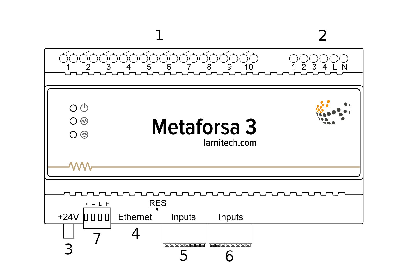
| 1 | — connector for load application |
| 2 | — connector for dimming-lamps application |
| 3 | — power connector |
| 4 | — Ethernet network connector |
| 5-6 | — connectors for universal input/output channels |
| 7 | — connector for expansion module. |
Overview of the METAFORSA device external connectors:
At the top of the casing (fig. 1) there is:
- connector (1) — Devices connection;
- connector (2) — Dimming lamps connection;
At the bottom of the casing (fig. 1) there is:
- connector (3) — module power supply connection;
- connector (4) — Ethernet network connection;
- connectors (5-6) — universal input/output channels connection – buttons, reed switches, LED buttons, leak sensors, motion sensors, temperature sensors, LED strips, 3-4-5 channel RGB strips, WS2812B strips, RS485 devices (Only for Metaforsa 3.plus);
- connector (7) — expansion module connection.
The physical configuration and contact point assignment of each connector are shown in table 2.
| Connector | Contact | Assignment |
|---|---|---|
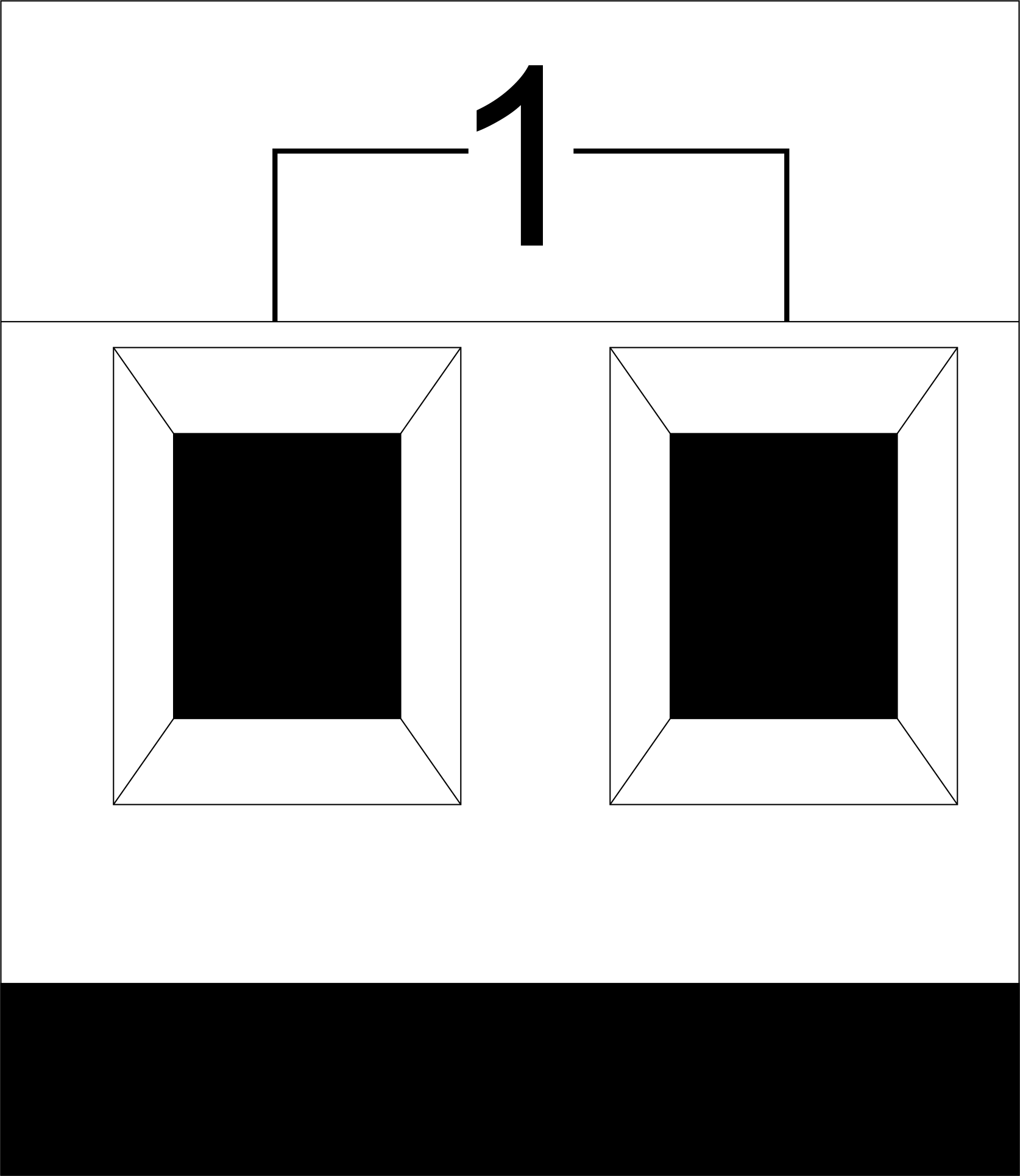 |
1-10 | Load application (light lamps, thermal actuators, etc.) |
| D1-4, L, N | Load application (dimming lamps) | |
| Device status indicators | The module status indicators are described in table 3 | |
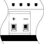 |
+24V GND |
+24V — module power supply by an external 24 V power supply GND — common |
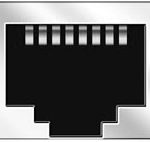 |
RJ45 | Connector for LAN connectivity |
| In1-14, In15-28 GND | Controlling devices connection (buttons, LED buttons, magnetic reed switches, motion detectors, leakage sensors, temperature sensors, etc.): In1 … In28 — logic inputs GND — common | |
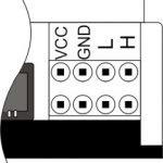 |
VCC GND L H |
External modules connection for CAN-bus VСС — 24V output for external devices power supply GND — common L — CAN-L data bus H — CAN-H data bus |
| Indicator | Status | Description |
|---|---|---|
| Power | Power | |
| Power not available | ||
| Activity | Data communication | |
| Data communication not available | ||
| Error | No errors | |
| Communication error | ||
| Module overheat | ||
| Dimmer outputs module overload | ||
| Absence of power on dimmers, if in configuration |
System installation and assembly
Before connecting the system, you must:
- site the sensor and actuators (if not pre-installed), set the sensors and actuators;
- site the module and power supply.
Note: The module must be installed near the power supply voltage source.
- The power of circuit breaker assembly must comply with the load capacity;
- Nothing else than the phase conductors can be connected to the module, the neutral wire is connected separately.
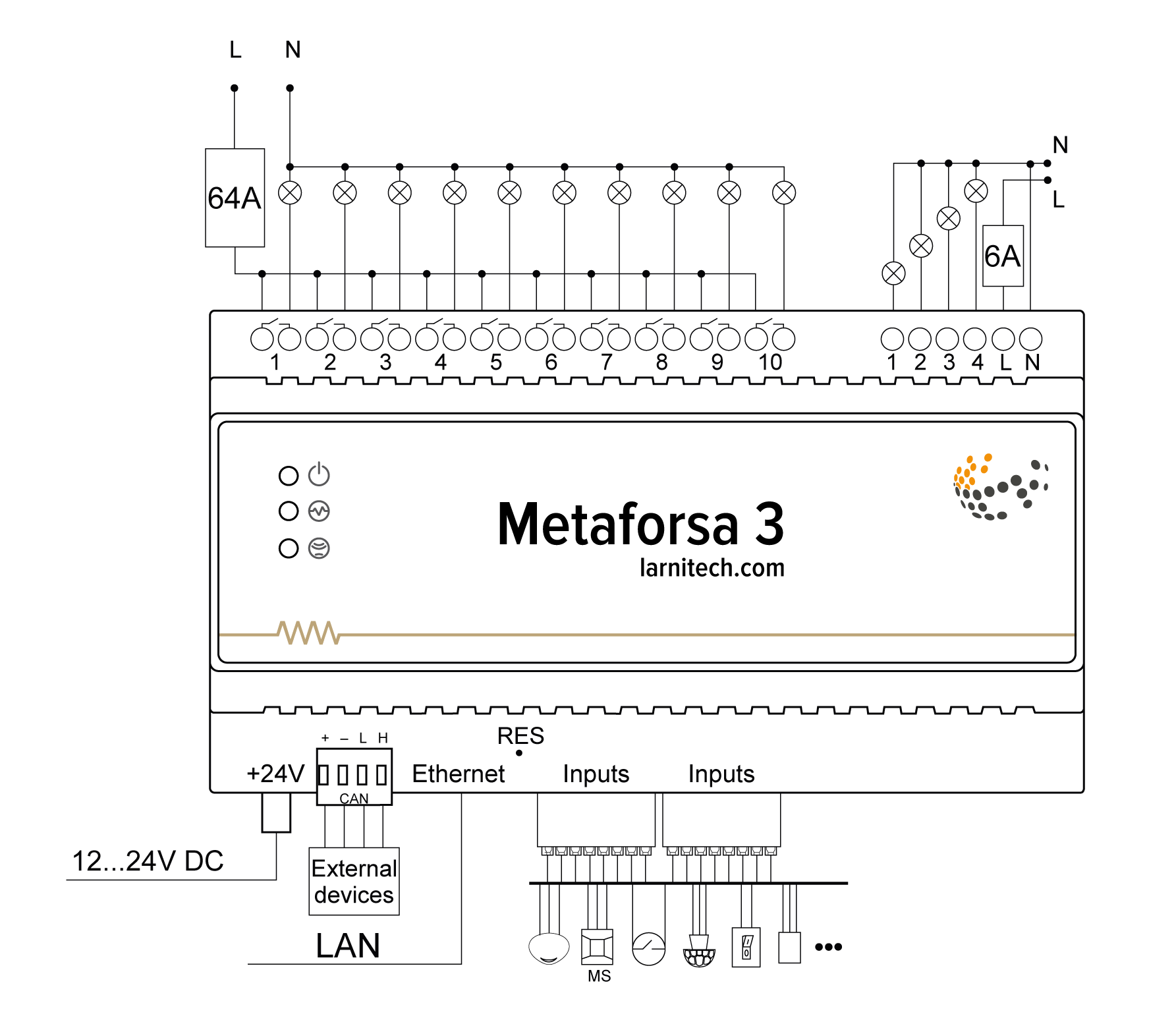
Typical diagram of METAFORSA 3/3.plus module connection is shown in fig. 3.
Connection of the actuators
Connection of the lights/electric contactor/heating thermal actuator
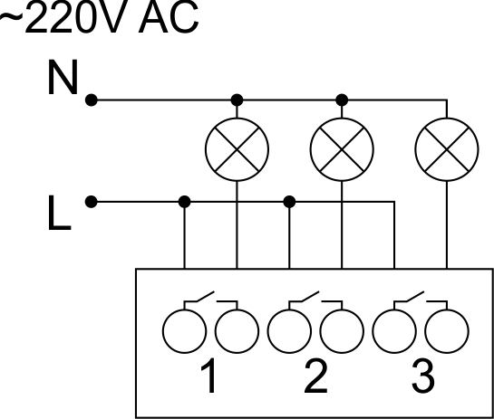 Fig. 4 |
Such actuators as light, electric contactor, heating thermal actuator should be switched on any of the outputs 1 – 10, the neutral wire and the ground wire should be connected directly to the switchboard. The example of connection is shown in Fig.4. |
Connection of high load device
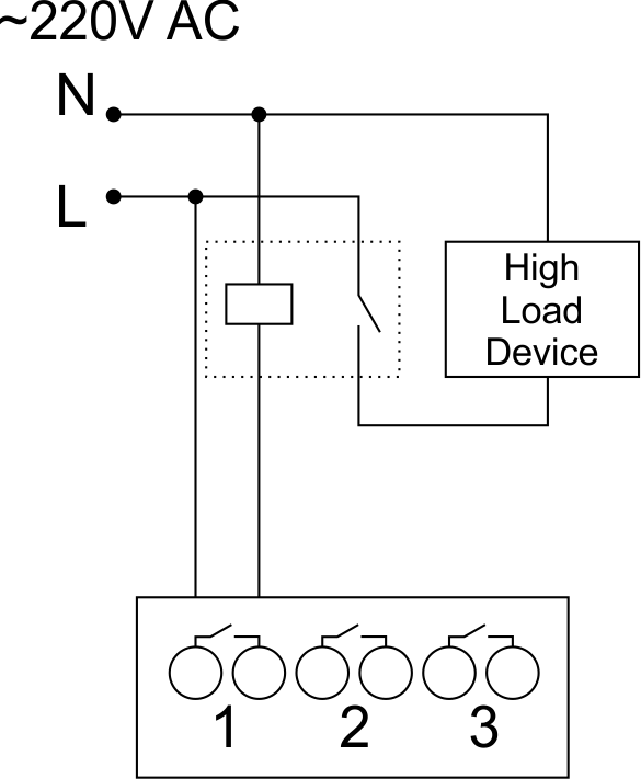 |
Recomended contactors:
|
Connection of single-pole water/gas supply valve
| Caution: Before applying power to the load, make sure that the output configuration of METAFORSA module is correct. The incorrect configuration or incorrect connection can cause the module failure and/or failure of the equipment connected to it, and even a fire. | |
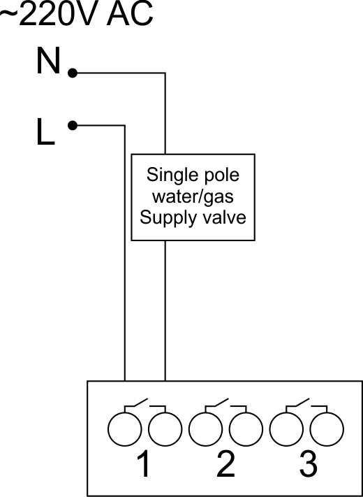 Fig. 5 |
The single pole water/gas supply valve is connected to any of the outputs of 1 – 10, the (neutral wire and the ground wire are connected directly to the switchboard. The example of connection is shown in Fig.5. |
Connection of double-pole water/gas supply valve
| Caution: Before applying power to the valve, it is necessary to ensure the output configuration of METAFORSA module is correct. The incorrect configuration can cause the voltage application simultaneously to both channels of the valve, which may result in the module failure and/or failure of the equipment connected to it, and even a fire. | |
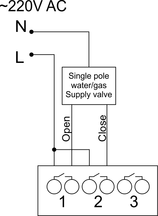 Fig. 6 |
Two adjacent contact points (for example, 3, 4) are used to connect the double-pole water/gas supply valve; in these conditions the neutral wire and the ground wire are connected directly to the switchboard. The example of connection is shown in Fig.6. |
Connection of single-pole gate actuator
| Caution: Before applying power to the module, you should properly configure access to the application. The contacts incorrectly configured can result in the module failure and/or failure of the equipment connected to it, and even a fire.
| |
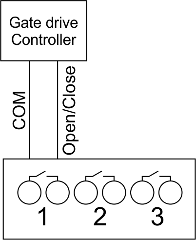 Fig. 7 |
Any contact point (for example, 3) is used to connect the single-pole gate drive controllers. The example of connection is shown in Fig.7. |
Connection of double-pole gate actuator
| Caution: Before applying power to the module, you must properly configure the outputs in the application. The contacts configured incorrectly can lead to simultaneous power supply to both channels, resulting in the module failure and/or failure of the equipment connected to it, and even a fire.
| |
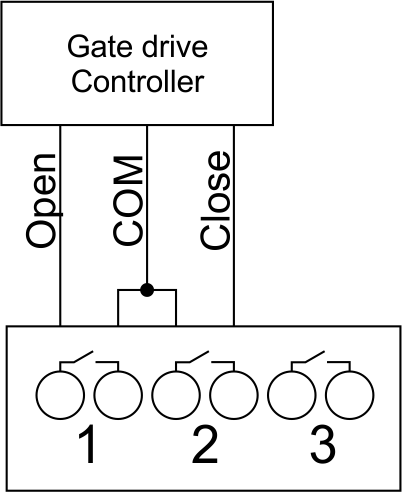 Fig. 8 |
Two adjacent contact points (for example, 3, 4) should be used to connect the double-pole gate drive controller. The example of connection is shown in Fig.8. |
Connection of curtain/jalousie/shutter actuator with 220V force control
| Caution: Before applying power to the module, you must properly configure the outputs in the application. The contacts configured incorrectly can lead to simultaneous power supply to both channels, resulting in the module failure and/or failure of the equipment connected to it, and even a fire.
| |
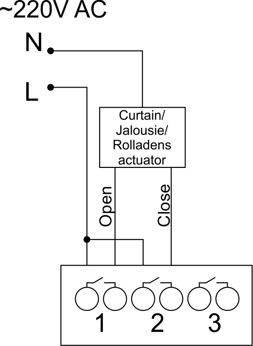 Fig. 9 |
Two adjacent contact points (for example, 3, 4) should be used to connect the curtain/jalousie/rolladens actuator, in these conditions the neutral wire and the ground wire are connected directly to the switchboard. The example of connection is shown in Fig.9. |
Connection of curtain/jalousie/shutter actuator with low-voltage control
| Caution: Before applying power to the module, you must properly configure the outputs in the application. The contacts configured incorrectly can lead to simultaneous power supply to both channels, resulting in the module failure and/or failure of the equipment connected to it, and even a fire.
| |
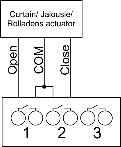 Fig. 10 |
Two adjacent contact points (for example, 3, 4) should be used to connect the curtain/jalousie/rolladens actuator with low-voltage control. The example of connection is shown in Fig.10. |
Connection of sensing elements/switches/buttons
Connection of motion sensors/leakage sensors
The motion sensors/leakage sensors should be connected to any free input in1-in28; in these conditions their power is connected to the contact points of +5V and GND of the relevant group. The example of connection is shown in Fig.11.
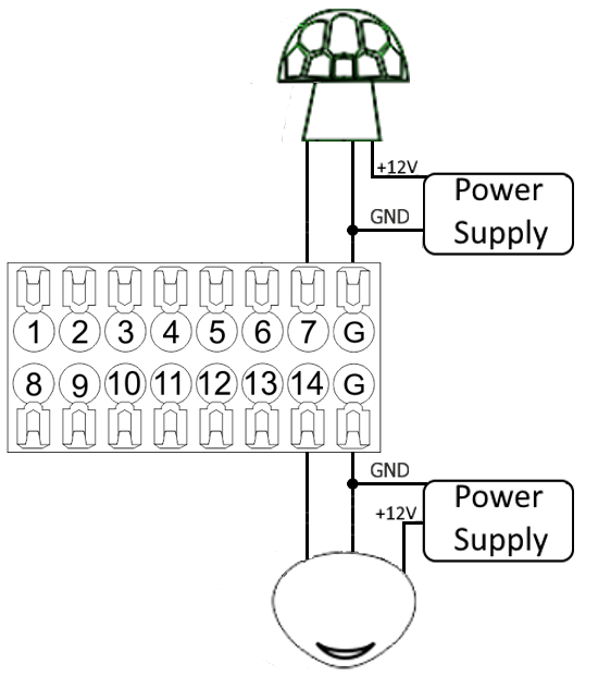
Fig. 11 connection of motion sensors/leakage sensors
Connection of buttons/switches/magnetic reed switches
Buttons and reed switches are connected to any free input in1-in28, while their second contact point is connected to GND point of the relevant METAFORSA module group. The example of connection is shown in Fig. 12-13.
 Fig. 12 connection of buttons/switching units |
 Fig. 13 connection of the magnetic reed switches (window/door position sensors) |
Connection of temperature sensors
Temperature sensors are connected to any free input in1-in28, while their second contact point is connected to GND point of the relevant METAFORSA module group. The example of connection is shown in Fig. 14.
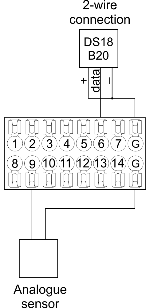
Fig. 14 connection of temperature sensors
RGB connection scheme

Fig. 15 RGB connection
WS2812B connection scheme
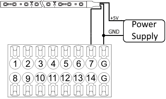
Fig. 16 WS2812B connection
RS485 connection scheme
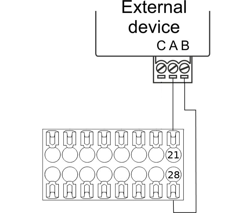
Fig. 17 RS485 connection
Connection of auxiliary equipment.
Expansion modules include Larnitech equipment connected through the CAN-bus. Such equipment includes: dimmers, RGB-backlit control modules, multimode sensors, etc. The equipment connected to the expansion port is defined automatically and does not require any preset tuning. Connector contact pin assignment is defined in Table 4. The example of connection is shown in Fig. 18.

|
| Caution! The 120 ohm terminating resistors should be installed at the end connectors between L and H contact points of CAN-bus. Ensure the connection is correct. The incorrect connection may cause sensor and/or module malfunction. |
Module installation and connection procedure
- Install the module in the switchboard on the DIN-rail and fix it with the special latch on the module base.
- Fasten the supply unit on the left side of the module.
- Connect the connector (4) having the noise filter pre-installed which is supplied complete with the module.
- Connect the connectors (5), (6).
- Connect the connectors (1), (2).
- Connect the connector (3).
- Apply power to the supply unit of METAFORSA module.
- Wait until the module is loaded, then configure it in accordance with the System Setup Instructions.
- Apply power to the connectors (1), (2).
- Check all equipment for proper operation.
METAFORSA module shut-off and deinstallation procedure
- De-energize the module by disconnecting the circuit breaker assembly of the load power supply and METAFORSA module supply unit. Verify the voltage is absent on the terminals (1), (2) of the connector wires and on the input terminals of the supply unit.
- Disconnect the load power supply connectors (1), (2).
- Disconnect the connector (3).
- Disconnect the connectors (4)-(6).
- Remove the module from the DIN-rail, releasing the latch at the bottom of the module base.
Hardware setup
To configure and control METAFORSA SMART HOUSE, you must install Larnitech software on your smartphone or tablet, which is available in App Store and Play Market. After installation, follow the System Setup Instructions.
Fault diagnostics and handling
The following are some possible faults and ways of fault handling. If you have any difficulty, or face the fault undeclared here, please contact the Technical Support: [1] or [support@larnitech.com]. There are also some tips in the FAQ section at our website [2].
The actuators do not operate:
- ensure the outputs are properly configured in the application (see System Setup Instructions);
- check the connection is correct in accordance with table 2 and paragraph 3.6;
- ensure the power is supplied to the input power contact , i.e. all circuit breaker assembly are ON.
- verify the operability of the connected equipment.
The module is off, indication absent:
- check the connection to 24V supply unit as shown in table 2 (contacts pin assignment);
- check the connection of the supply unit to 220V power mains, the indicator should be ON.
Network connection fault:
- ensure the Ethernet cable is properly wired and connected to the connector;
- ensure the LED status indicators are ON on the Ethernet connector;
- check the LAN configuration is correct, Ethernet cable loops are absent;
- METAFORSA module and the device you are connecting from are in the same network.
hold integer 0-10000 1-10 by default hold is the same as runtime hold is the bridging time in miliseconds, is used for gate and jalousie, lock; Example: hold=3500
The sensors do not operate:
- ensure the inputs are properly configured in the application (System Setup Instructions);
- check the connection is correct in accordance with table 2 and paragraph 3.7;
- ensure the METAFORSA module is ON: circuit breaker assembly is closed, indication on the supply unit is ON, the module indication corresponds to the operating status – table 3;
- check the power supply availability on the sensors;
- check the integrity of lines laid to the sensors.
The auxiliary equipment does not operate:
- check the connection is correct in accordance with table 2 and paragraph 3.8-9;
- ensure the METAFORSA module is ON: circuit breaker assembly is closed, indication on the supply unit is ON, the module indication corresponds to the operating status – table 3;
- check the integrity of the CAN lines, voltage supply on the modules.
HW Settings
| Name | Type, range | SUBID | Default | Description |
|---|---|---|---|---|
| runtime | integer 0-100 | 1-10 | 15 | runtime is the open/close time in seconds, is used for jalousie, gate, valve(2 pole);
|
| runtimeopen | integer 0-60000 | Blinds subId | Runtimeopen is the open time in milliseconds, is used for blinds; Example: runtimeopen=15000 | |
| runtimeclose | integer 0-60000 | Blinds subId | Runtimeclose is the close time in milliseconds, is used for blinds; Example: runtimeclose=15000 | |
| hold | integer 0-10000 | 1-10 | 500 | hold is the bridging time in milliseconds, is used for gate and jalousie (by default hold is the same as runtime for jalousie and gate), lock; Example: hold=3500 |
| def | string 'ON' | 1-10 | 'OFF' | def is the element status is set after restart, is used for lamp, heating, valve(1 pole); Example: def='ON' |
| stop | Char ‘R’ | 1-7 | – | (for 2-pole gate and blinds) If it is declared then by Stop command during the motion, the same impulse appears as it was at the beginning of the motion. Pole, an which the stop-impules is formed, is defined by the parameter Stop value. If it is ‘r’ or ‘R’ then stop-impulse is produced on the opposite to the start-impulse pole. If any other value is delcared (e.g., ‘d’ ) then the stop-impulse is on the same pole. If a Runtime passed after the beginning of the motion then the stop-impulse is not formed. Example: stop=’r’ |
| out | char[10] | 98 | 'LLLLHHHHP-' | Each char is responsible for the type of a particular channel
Example: out='LLB-G-V-W-' |
| dm | char[4] | 98 | ‘LLLL’ | Each char is responsible for the type of a particular channel
Example: dm=’skl-‘ |
| def | integer 0-250 | 11-14 | 100 | The default brightness level in case of a power reset (1..250). Example: def=250 |
| min | integer 0-100 | 11-14 | 0 | Minimum dimming level, example: min=10 |
| max | integer 0-100 | 11-14 | 100 | Maximum dimming level, example max=95 |
| start | integer 0-100 | 11-14 | 0 | The Start function is used for lamps that lack the minimal voltage to get turned on. If the set value is lower than the start value, the lamp is turned on at the start value and them the light is dimmed down to the set level. Example: start=60 |
| force | integer 0-100 | 11-14 | 10 | Time duration of the starting value (measured in milliseconds). Example: force=20 |
| runtime | integer 0-60000 | 11-14 | 1000 | Runtime is the speed of changing the brightness from ‘min’ to ‘max’ (measured in milliseconds). Example: runtime=1000 |
| offset | integer (+/- 0…39) | 39-46 | '0' | sensor values offset; For example, offset is -3.8 :
Example: hw="offset='-3.8'" |
| io | char[28] | 98 | io='KKKKKKKKKKKKKKKKKKKKKKKKKKKK' | Each char is responsible for the type of a particular channel
Example: io='KKKKKKKKKKKKKKKKKKKKKKKKKKKK' |
| Only for Metaforsa 3.plus | ||||
| cfg | string | 98 | 9600/8N1 | cfg='SPEED/BPS', where
Example: 1hw="cfg='9600/8N1'"
|
| [Protocol] | string | 98 | — | Protocol setting is described by protocol parameter. The following
protocols are supported:
Example: 1hw="cfg='9600/8N1' modbus"
|
| echo | on; off | 98 | 'off' | For settings check out and testing echo parameter can be used. Module
echo-reply can be turned on or off with the help of this parameter.Echo parameter value:
Example: 1hw="cfg='9600/8N1' echo='off'"
|
 1		<item addr="349:1" auto-period="600" cfgid="197" name="Lamp 1" type="lamp"/>
 2		<item addr="349:2" auto-period="600" cfgid="197" name="Lamp 2" type="lamp"/>
 3		<item addr="349:3" auto-period="600" cfgid="197" name="Lamp 3" type="lamp"/>
 4		<item addr="349:4" auto-period="600" cfgid="197" name="Lamp 4" type="lamp"/>
 5		<item addr="349:5" auto-period="600" cfgid="197" name="Lamp 5" type="lamp"/>
 6		<item addr="349:6" cfgid="197" name="Radiator" temperature-lag="0.2" type="valve-heating">
 7			<automation name="Eco" temperature-level="16"/>
 8			<automation name="Comfort" temperature-level="22"/>
 9			<automation name="Hot" temperature-level="25"/>
10		</item>
11		<item addr="349:7" cfgid="197" name="Radiator" temperature-lag="0.2" type="valve-heating">
12			<automation name="Eco" temperature-level="16"/>
13			<automation name="Comfort" temperature-level="22"/>
14			<automation name="Hot" temperature-level="25"/>
15		</item>
16		<item addr="349:8" cfgid="197" name="Radiator" temperature-lag="0.2" type="valve-heating">
17			<automation name="Eco" temperature-level="16"/>
18			<automation name="Comfort" temperature-level="22"/>
19			<automation name="Hot" temperature-level="25"/>
20		</item>
21		<item addr="349:9" cfgid="197" name="Jalousie" sub-type="120" type="jalousie"/>
22		<item addr="349:11" auto-period="600" cfgid="197" name="Dimmer 1" type="dimmer-lamp"/>
23		<item addr="349:12" auto-period="600" cfgid="197" name="Dimmer 2" type="dimmer-lamp"/>
24		<item addr="349:13" auto-period="600" cfgid="197" name="Dimmer 3" type="dimmer-lamp"/>
25		<item addr="349:14" auto-period="600" cfgid="197" name="Dimmer 4" type="dimmer-lamp"/>
26		<item addr="349:16" cfgid="197" name="Door 1" type="door-sensor"/>
27		<item addr="349:17" cfgid="197" name="Door 2" type="door-sensor"/>
28		<item addr="349:18" cfgid="197" name="Door 3" type="door-sensor"/>
29		<item addr="349:19" cfgid="197" name="Door 4" type="door-sensor"/>
30		<item addr="349:20" cfgid="197" name="Door 5" type="door-sensor"/>
31		<item addr="349:21" cfgid="197" name="Door 6" type="door-sensor"/>
32		<item addr="349:22" cfgid="197" name="Door 7" type="door-sensor"/>
33		<item addr="349:23" cfgid="197" name="Door 8" type="door-sensor"/>
34		<item addr="349:24" cfgid="197" name="Door 9" type="door-sensor"/>
35		<item addr="349:25" cfgid="197" name="Door 10" type="door-sensor"/>
36		<item addr="349:26" cfgid="197" name="Door 11" type="door-sensor"/>
37		<item addr="349:27" cfgid="197" name="Door 12" type="door-sensor"/>
38		<item addr="349:28" cfgid="197" name="Door 13" type="door-sensor"/>
39		<item addr="349:29" cfgid="197" name="Door 14" type="door-sensor"/>
40		<item addr="349:30" cfgid="197" name="Door 15" type="door-sensor"/>
41		<item addr="349:31" cfgid="197" name="Door 16" type="door-sensor"/>
42		<item addr="349:32" cfgid="197" name="Door 17" type="door-sensor"/>
43		<item addr="349:33" cfgid="197" name="Door 18" type="door-sensor"/>
44		<item addr="349:34" cfgid="197" name="Door 19" type="door-sensor"/>
45		<item addr="349:35" cfgid="197" name="Door 20" type="door-sensor"/>
46		<item addr="349:36" cfgid="197" name="Door 21" type="door-sensor"/>
47		<item addr="349:37" cfgid="197" name="Door 22" type="door-sensor"/>
48		<item addr="349:38" cfgid="197" name="Door 23" type="door-sensor"/>
49		<item addr="349:39" cfgid="197" name="Door 24" type="door-sensor"/>
50		<item addr="349:40" cfgid="197" name="Door 24" type="door-sensor"/>
51		<item addr="349:41" cfgid="197" name="Door 25" type="door-sensor"/>
52		<item addr="349:43" cfgid="197" name="IR receiver" type="ir-receiver"/>
53		<item addr="349:44" cfgid="197" name="RS485" type="com-port"/>
54		<item addr="349:90" cfgid="197" name="Current" system="yes" type="current-sensor"/>
55		<item addr="349:95" cfgid="197" name="Temperature" system="yes" type="temperature-sensor"/>
56		<item addr="349:96" cfgid="197" name="Temperature" system="yes" type="temperature-sensor"/>
57		<item addr="349:97" cfgid="197" name="Temperature" system="yes" type="temperature-sensor"/>
58		<item addr="349:98" cfgid="197" hw="out='LLLLLHHHB-' dm='LLLL' io='KKKKKKKKKKKKKKKKKKKKUKKKKKK-'" logic-ver="19" name="Temperature" sn="2533726919" system="yes" type="temperature-sensor"/>
59		<item addr="349:100" cfgid="197" name="RS232" type="com-port"/>