Difference between revisions of "Metaforsa2 MF-14/es"
(Created page with "===Especificaciones técnicas básicas del Sistema===") Tags: Mobile web edit Mobile edit |
(Created page with "Las especificaciones y características básicas del módulo METAFORSA MF-14.A se muestran en la tabla 1 {| clase="wikitabla" |+ estilo="text-align:izquierda;" | Tabla 1 |- !E...") Tags: Mobile web edit Mobile edit |
||
| Line 146: | Line 146: | ||
===Especificaciones técnicas básicas del Sistema=== | ===Especificaciones técnicas básicas del Sistema=== | ||
| − | + | Las especificaciones y características básicas del módulo METAFORSA MF-14.A se muestran en la tabla 1 | |
| − | {| | + | {| clase="wikitabla" |
| − | |+ | + | |+ estilo="text-align:izquierda;" | Tabla 1 |
|- | |- | ||
| − | ! | + | !Especificación !! Significado |
|- | |- | ||
| − | |colspan="2"|''' | + | |colspan="2"|'''Puertos de salida''' |
|- | |- | ||
| − | | | + | | Número de canales conmutados || 10 |
|- | |- | ||
| − | | | + | | Número de grupos conmutados|| 10 |
|- | |- | ||
| − | | | + | | Número de canales de regulación || 4 |
|- | |- | ||
| − | | | + | | Tensión de conmutación || 0-250 V CA/CC |
|- | |- | ||
| − | | | + | | Carga máxima (un canal) || 16A |
|- | |- | ||
| − | | | + | | Carga máxima (dispositivo) || 160A |
|- | |- | ||
| − | | | + | | Carga máxima por canal de regulación || 0,5 A (110 W a 220 V) |
|- | |- | ||
| − | | | + | | Tipo de atenuador || MOSFET |
|- | |- | ||
| − | | | + | | Tipo de carga de atenuador || R,C |
|- | |- | ||
| − | | | + | | Tipo de atenuación || borde de salida |
|- | |- | ||
| − | | | + | | Tipo de conexión del cable de alimentación || conector |
|- | |- | ||
| − | | | + | |Sección permitida del cable de alimentación a conectar en la toma de corriente:<br>cable monoconductor<br>cable multiconductor<br>cable multiconductor con punta||<br>0,5 … 4mm2<br>0,5 … 4mm2<br >0,5 … 2,5 mm2 |
|- | |- | ||
| − | |colspan="2"|''' | + | |colspan="2"|'''Puertos de entrada''' |
|- | |- | ||
| − | | | + | |Número de entradas discretas || 24 |
| − | |||
| − | |||
|- | |- | ||
| − | | | + | |Número de entradas digitales || 4 |
|- | |- | ||
| − | | | + | |Clasificación máxima actual de los conectores de tensión de corriente continua || 50mA |
|- | |- | ||
| − | | | + | |colspan="2"|'''Otro''' |
|- | |- | ||
| − | | | + | |Temperatura ambiente de funcionamiento || 0 … +45°С |
|- | |- | ||
| − | | | + | |Temperatura de almacenamiento/transporte || -20 … +60°С |
|- | |- | ||
| − | | | + | |Humedad permitida || 0 … 95% (sin condensación) |
|- | |- | ||
| − | | | + | |Fuente de alimentación || 12 … 27,5 V CC<br>24 V, 0,75 A Recomendado |
|- | |- | ||
| − | | | + | |Máxima demanda || 0.5А |
|- | |- | ||
| − | | | + | |Interfaces disponibles || Ethernet, CAN, OneWire |
|- | |- | ||
| − | |CAN (4 | + | |Tipo de autobús || CAN (4 hilos) |
|- | |- | ||
| − | |CAN | + | |CAN (4 hilos) || 800 m* (par trenzado 5 cat) |
|- | |- | ||
| − | |CAN | + | |Tipo de cable CAN || FTP Gato 5E |
|- | |- | ||
| − | | | + | |Tipo de conexión CAN || conector |
|- | |- | ||
| − | | | + | |Longitud máxima de la línea digital || 30 metros |
|- | |- | ||
| − | | | + | |Tipo de cable de línea digital || UTP/FTP Categoría 5E |
|- | |- | ||
| − | |LAN | + | |Longitud máxima de LAN || 100 metros |
|- | |- | ||
| − | |LAN | + | |Tipo de cable LAN || UTP/FTP Categoría 5E |
|- | |- | ||
| − | | | + | |Tipo de conexión LAN || Conector RJ-45 |
|- | |- | ||
| − | | | + | |Especificaciones dimensionales || 9U, 156x110x58mm |
|- | |- | ||
| − | | | + | |Material de la carcasa || Plástico ABS |
|- | |- | ||
| − | | | + | |Carcasa || IP40 |
|- | |- | ||
| − | | | + | |Tipo de instalación del equipo || Carril DIN (EN 60715) |
| + | |- | ||
| + | |Peso || 400 gramos | ||
|} | |} | ||
| − | <nowiki>*</nowiki> – | + | <nowiki>*</nowiki> – se requiere la instalación de unidades de suministro de energía adicionales para líneas largas; La longitud máxima de la línea puede verse reducida por varios factores de interferencia. |
===General structure of the System=== | ===General structure of the System=== | ||
Revision as of 08:03, 4 March 2024
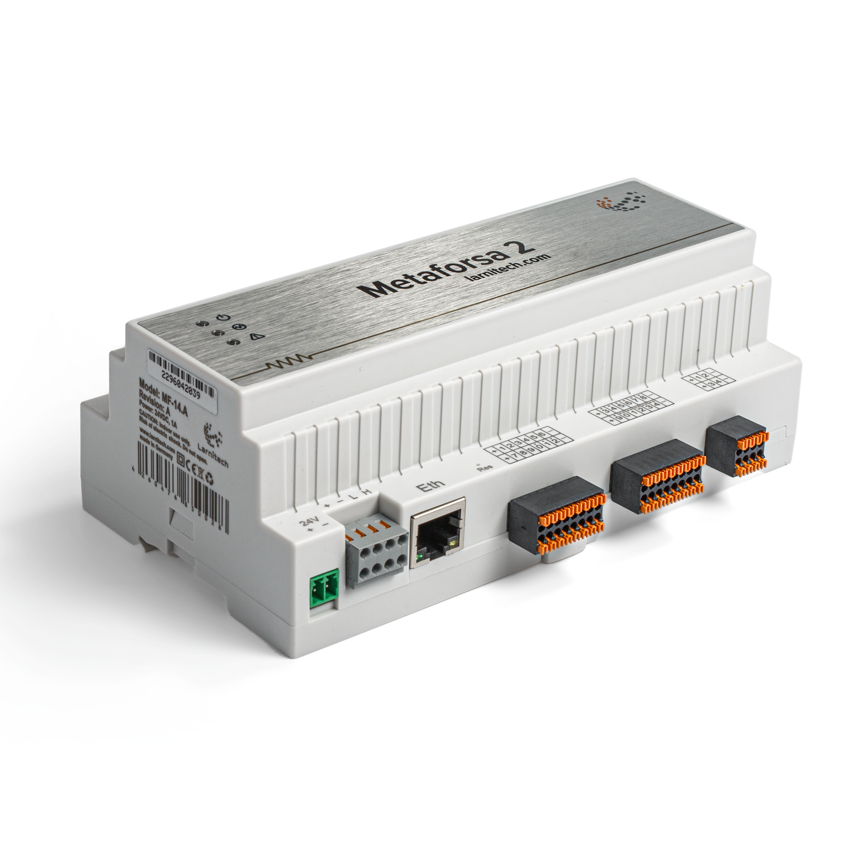
| MF-14 | |||||||||||||
|---|---|---|---|---|---|---|---|---|---|---|---|---|---|
 | |||||||||||||
| |||||||||||||
| |||||||||||||
| |||||||||||||
Introducción
El Manual de Instalación de METAFORSA SMART HOUSE describe el procedimiento para su instalación, montaje, funcionamiento y configuración. Mientras trabaja con el sistema, debe cumplir estrictamente con todos los requisitos establecidos en este manual. El incumplimiento puede provocar daños al dispositivo, fallos, descargas eléctricas, incendios y otras consecuencias. El fabricante se reserva el derecho de realizar cambios en este manual sin previo aviso. Este manual es una parte integral del sistema y permanecerá en manos del cliente final.
Características
- 10 salidas universales compatibles:
- Luces
- Válvulas de calefacción NC/NO
- Persianas
- Puertas de 1 o 2 polos
- Válvulas de 1 o 2 polos
- Cerraduras NC/NO
- Unidades fancoil
- 4 salidas de atenuación
- 24 entradas discretas que soportan:
- Botones
- Interruptores
- interruptores de láminas
- sensores de fugas
- detectores de movimiento
- 4 entradas digitales para hasta 8 sensores de temperatura
- Puerto de extensión
- Relés con contactos AgSnO2 clasificados para corriente de entrada de 80 A y 20 ms
- Conexión a la nube y control de todos los sistemas de la casa.
- Control por voz (Siri, Alexa, Google Home)
- El motor de complementos permite ampliar las posibilidades del sistema (por ejemplo, integración con luces Satel, Philips Hue, IKEA)
- Seguridad contra intrusiones no autorizadas garantizada con cifrado RSA/AES256
- Notificaciones push del sistema en su teléfono (también es posible recibirlas a través de mensajeros de Telegram y Viber)
- Historial (se almacenan los datos del medidor durante 1 año)
- Plug and play (posibilidad de ampliación del sistema rápida y fácil de usar)
- Actualizaciones periódicas del sistema
- Gran base de datos de scripts constantemente actualizada para satisfacer todas sus necesidades
- Copias de seguridad diarias automáticas vía nube con posibilidad de restaurar la configuración inicial
- API abierta (que permite integrar Larnitech a otros sistemas)
- Interfaz web LT SETUP interactiva y fácil de usar disponible para configuración avanzada
- Conecta y reproduce
- Es un kit de sistema Smart Home completamente listo para instalar.
Requisitos de seguridad
Para evitar el riesgo de incendio, descarga eléctrica, daños al sistema y/o lesiones personales, la instalación y el montaje del sistema deben realizarse de acuerdo con las instrucciones que se enumeran a continuación:
- todos los trabajos de conexión deben realizarse sin energía eléctrica;
- utilizar herramientas adecuadas y protección personal contra descargas eléctricas;
- no utilice cables, alambres ni conectores dañados;
- evitar el plegado de cables y alambres;
- No pellizque ni doble los cables aplicando fuerza excesiva. De lo contrario, los conductores internos del cable y los alambres podrían pelarse o romperse;
- no utilice una toma de corriente con malos contactos para realizar la conexión;
- no exceda el límite de parámetros de carga especificados en este manual;
- La sección de los cables de los conductores de alimentación está sujeta a las especificaciones de límite de densidad de corriente, tipo de aislamiento y material del cable. La sección ligera puede provocar un sobrecalentamiento del cable y un incendio.
Al trabajar con el sistema después del suministro de voltaje NUNCA:
- realizar conexión/desconexión de conectores;
- abrir módulos y sensores.
Configuración y propósito del sistema
Propósito del sistema
METAFORSA SMART HOUSE es una solución lista para usar para la automatización de locales residenciales, comerciales y complejos hoteleros que incluye las características más deseadas de Smart House.
El dispositivo tiene 10 canales de control, 4 canales de atenuación, 24 canales de sensores entrantes y un puerto de conexión de sensores digitales.
| Las salidas universales se pueden utilizar para controlar: | Las entradas universales le permiten conectar: |
|---|---|
| Iluminación | Botones/unidades de conmutación |
| Conectores hembra | Interruptores de láminas magnéticos |
| Calefacción por suelo radiante | Sensores de movimiento |
| Actuadores de cortinas/portones | Sensores de fugas |
| Válvulas de suministro de agua/calefacción |
Puerto de conexión de sensores digitales
El puerto de conexión de sensores digitales le permite conectar una variedad de sensores digitales, como sensores de temperatura, luz ambiental, humedad y otros.
Puerto de expansión
El puerto de expansión le permite actualizar el sistema conectando equipos auxiliares, como el módulo de control para iluminación LED, atenuación, dispositivos de medición y otros elementos.
El paquete, que está completamente listo para instalar, incluye el hardware y el software básicos.
Contenido del paquete
El paquete viene de serie con:
| Unidad central METAFORSA MF-14.А | 1 PC |
| Unidad de fuente de alimentación MEANWELL DR-15-12 | 1 PC |
| Sensor de movimiento CW-MSD | 3 piezas |
| Sensor de fugas FW-WL.A | 2 piezas |
| Elemento sensible a la temperatura FW-TS.A | 4 piezas |
| Interruptor de láminas magnético (sensor de posición de ventana/puerta) | 4 piezas |
| Filtro de ruido del cable Ethernet | 1 PC |
| Cable de alimentación | 1 PC |
Especificaciones técnicas básicas del Sistema
Las especificaciones y características básicas del módulo METAFORSA MF-14.A se muestran en la tabla 1
| Especificación | Significado |
|---|---|
| Puertos de salida | |
| Número de canales conmutados | 10 |
| Número de grupos conmutados | 10 |
| Número de canales de regulación | 4 |
| Tensión de conmutación | 0-250 V CA/CC |
| Carga máxima (un canal) | 16A |
| Carga máxima (dispositivo) | 160A |
| Carga máxima por canal de regulación | 0,5 A (110 W a 220 V) |
| Tipo de atenuador | MOSFET |
| Tipo de carga de atenuador | R,C |
| Tipo de atenuación | borde de salida |
| Tipo de conexión del cable de alimentación | conector |
| Sección permitida del cable de alimentación a conectar en la toma de corriente: cable monoconductor cable multiconductor cable multiconductor con punta |
0,5 … 4mm2 0,5 … 4mm2 0,5 … 2,5 mm2 |
| Puertos de entrada | |
| Número de entradas discretas | 24 |
| Número de entradas digitales | 4 |
| Clasificación máxima actual de los conectores de tensión de corriente continua | 50mA |
| Otro | |
| Temperatura ambiente de funcionamiento | 0 … +45°С |
| Temperatura de almacenamiento/transporte | -20 … +60°С |
| Humedad permitida | 0 … 95% (sin condensación) |
| Fuente de alimentación | 12 … 27,5 V CC 24 V, 0,75 A Recomendado |
| Máxima demanda | 0.5А |
| Interfaces disponibles | Ethernet, CAN, OneWire |
| Tipo de autobús | CAN (4 hilos) |
| CAN (4 hilos) | 800 m* (par trenzado 5 cat) |
| Tipo de cable CAN | FTP Gato 5E |
| Tipo de conexión CAN | conector |
| Longitud máxima de la línea digital | 30 metros |
| Tipo de cable de línea digital | UTP/FTP Categoría 5E |
| Longitud máxima de LAN | 100 metros |
| Tipo de cable LAN | UTP/FTP Categoría 5E |
| Tipo de conexión LAN | Conector RJ-45 |
| Especificaciones dimensionales | 9U, 156x110x58mm |
| Material de la carcasa | Plástico ABS |
| Carcasa | IP40 |
| Tipo de instalación del equipo | Carril DIN (EN 60715) |
| Peso | 400 gramos |
* – se requiere la instalación de unidades de suministro de energía adicionales para líneas largas; La longitud máxima de la línea puede verse reducida por varios factores de interferencia.
General structure of the System
Module general view is shown in fig. 1

| 1 | — connector for load application |
| 2 | — connector for dimming-lamps application |
| 3 | — power connector |
| 4 | — Ethernet network connector |
| 5-6 | — connectors for digital sensors and buttons/switching units |
| 7 | — OneWire interface connector (for digital sensors) |
| 8 | — connector for expansion module. |
Overview of the METAFORSA device external connectors:
At the top of the casing (fig. 1) there is:
- connector (1) — Devices connection;
- connector (2) — Dimming lamps connection;
At the bottom of the casing (fig. 1) there is:
- connector (3) — module power supply connection;
- connector (4) — Ethernet network connection;
- connectors (5-6) — four six-point connectors for digital sensors connection – motion, leakage, reed switch sensors, and *button/switching unit sensors;
- connector (7) — OneWire digital sensors bus connection;
- connector (8) — expansion module connection.
The physical configuration and contact point assignment of each connector are shown in table 2.
| Connector | Contact | Assignment |
|---|---|---|
 |
1-10 | Load application (light lamps, thermal actuators, etc.) |
| D1-4, L, N | Load application (dimming lamps) | |
| Device status indicators | The module status indicators are described in table 3 | |
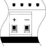 |
+24V GND |
+24V — module power supply by an external 24 V power supply GND — common |
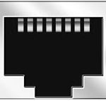 |
RJ45 | Connector for LAN connectivity |
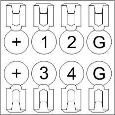
| In1-12, In13-24 GND | Controlling devices connection (buttons, magnetic reed switches, motion or leakage sensors): +12V — sensor power output +12 V In1 … In24 — logic inputs (0-12 V) GND — common | |
 |
OneWire | Digital sensors connection (temperature) VCC — sensors power supply output +5V OW1-OW4 — OneWire data buses GND — common |
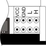 |
VCC GND L H |
External modules connection for CAN-bus VСС — 24V output for external devices power supply GND — common L — CAN-L data bus H — CAN-H data bus |
| Indicator | Status | Description |
|---|---|---|
| Power | Power | |
| Power not available | ||
| Activity | Data communication | |
| Data communication not available | ||
| Error | No errors | |
| Communication error | ||
| Module overheat | ||
| Dimmer outputs module overload | ||
| Absence of power on dimmers, if in configuration |
System installation and assembly
Before connecting the system, you must:
- site the sensor and actuators (if not pre-installed), set the sensors and actuators;
- site the module and power supply.
Note: The module must be installed near the power supply voltage source.
- The power of circuit breaker assembly must comply with the load capacity;
- Nothing else than the phase conductors can be connected to the module, the neutral wire is connected separately.
Typical diagram of METAFORSA MF-14.A module connection is shown in fig. 3.

Connection of the actuators
Connection of the lights/electric contactor/heating thermal actuator
 Fig. 4 |
Such actuators as light, electric contactor, heating thermal actuator should be switched on any of the outputs 1 – 10, the neutral wire and the ground wire should be connected directly to the switchboard. The example of connection is shown in Fig.4. |
Connection of high load device
 |
Recomended contactors:
|
Connection of single-pole water/gas supply valve
| Caution: Before applying power to the load, make sure that the output configuration of METAFORSA module is correct. The incorrect configuration or incorrect connection can cause the module failure and/or failure of the equipment connected to it, and even a fire. | |
 Fig. 5 |
The single pole water/gas supply valve is connected to any of the outputs of 1 – 10, the (neutral wire and the ground wire are connected directly to the switchboard. The example of connection is shown in Fig.5. |
Connection of double-pole water/gas supply valve
| Caution: Before applying power to the valve, it is necessary to ensure the output configuration of METAFORSA module is correct. The incorrect configuration can cause the voltage application simultaneously to both channels of the valve, which may result in the module failure and/or failure of the equipment connected to it, and even a fire. | |
 Fig. 6 |
Two adjacent contact points (for example, 3, 4) are used to connect the double-pole water/gas supply valve; in these conditions the neutral wire and the ground wire are connected directly to the switchboard. The example of connection is shown in Fig.6. |
Connection of single-pole gate actuator
| Caution: Before applying power to the module, you should properly configure access to the application. The contacts incorrectly configured can result in the module failure and/or failure of the equipment connected to it, and even a fire.
| |
 Fig. 7 |
Any contact point (for example, 3) is used to connect the single-pole gate drive controllers. The example of connection is shown in Fig.7. |
Connection of double-pole gate actuator
| Caution: Before applying power to the module, you must properly configure the outputs in the application. The contacts configured incorrectly can lead to simultaneous power supply to both channels, resulting in the module failure and/or failure of the equipment connected to it, and even a fire.
| |
 Fig. 8 |
Two adjacent contact points (for example, 3, 4) should be used to connect the double-pole gate drive controller. The example of connection is shown in Fig.8. |
Connection of curtain/jalousie/shutter actuator with 220V force control
| Caution: Before applying power to the module, you must properly configure the outputs in the application. The contacts configured incorrectly can lead to simultaneous power supply to both channels, resulting in the module failure and/or failure of the equipment connected to it, and even a fire.
| |
 Fig. 9 |
Two adjacent contact points (for example, 3, 4) should be used to connect the curtain/jalousie/rolladens actuator, in these conditions the neutral wire and the ground wire are connected directly to the switchboard. The example of connection is shown in Fig.9. |
Connection of curtain/jalousie/shutter actuator with low-voltage control
| Caution: Before applying power to the module, you must properly configure the outputs in the application. The contacts configured incorrectly can lead to simultaneous power supply to both channels, resulting in the module failure and/or failure of the equipment connected to it, and even a fire.
| |
 Fig. 10 |
Two adjacent contact points (for example, 3, 4) should be used to connect the curtain/jalousie/rolladens actuator with low-voltage control. The example of connection is shown in Fig.10. |
Connection of sensing elements/switches/buttons
Connection of motion sensors
The motion sensors should be connected to any free input in1-in24; in these conditions their power is connected to the contact points of +12V and GND of the relevant group. The example of connection is shown in Fig.11.

Fig. 11
Connection of FW-WL.A leakage sensors
FW-WL.A leakage sensors are connected to any free input in1 – in24, in these conditions the power should be connected to +12V and GND points of the relevant group. The example of connection is shown in fig. 12.
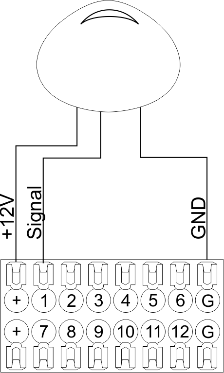 Fig12 |
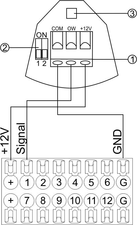 Fig13 |
Configuration and connection of the FW-WL.A sensor 1. Terminals:
- +12V — sensor power is connected to the contact point of METAFORSA “+12V”;
- OW — sensor pickup signal;
- GND — common, connected to GND contact of METAFORSA.
2. Sensor preset switch (optionally):
- 1 — sensor sensitivity (ON – high, OFF – low);
- 2 — indicator colour setting (ON – blue, OFF – green).
3. LED status indicator.
Connection of buttons/switches/magnetic reed switches
Buttons and reed switches are connected to any free input in1-in24, while their second contact point is connected to GND point of the relevant METAFORSA module group, + 12V power outputs – not in use. The example of connection is shown in Fig. 14-15.
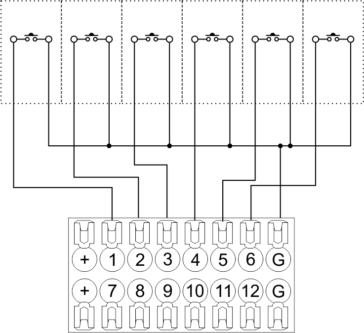 Fig14 connection of buttons/switching units |
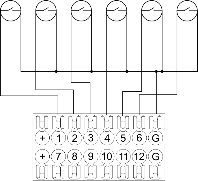 Fig15 connection of the magnetic reed switches (window/door position sensors) |
Connection of digital sensors
The OW adapter (Fig. 16a) is supplied along with METAFORSA module with the possibility to connect up to 8 digital sensors to it. In these conditions, several devices can be connected to one channel (Fig. 16b). The connected sensors are detected automatically and do not require any original setting.
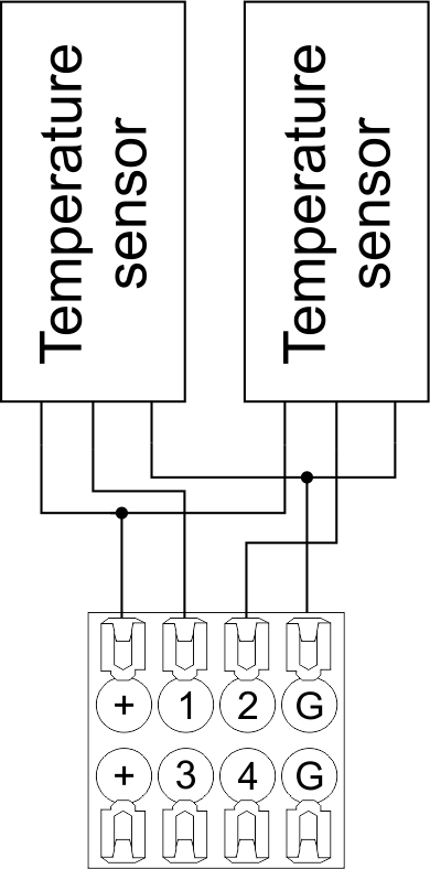 Fig16 a |
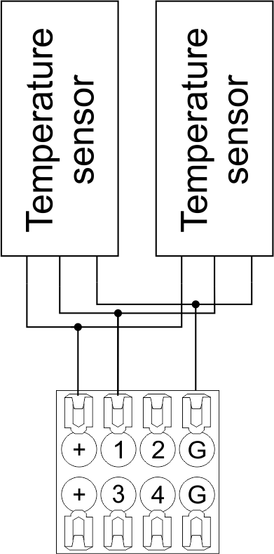 Fig16 b |
Configuration and connection of the OW adapter
Connection of auxiliary equipment.
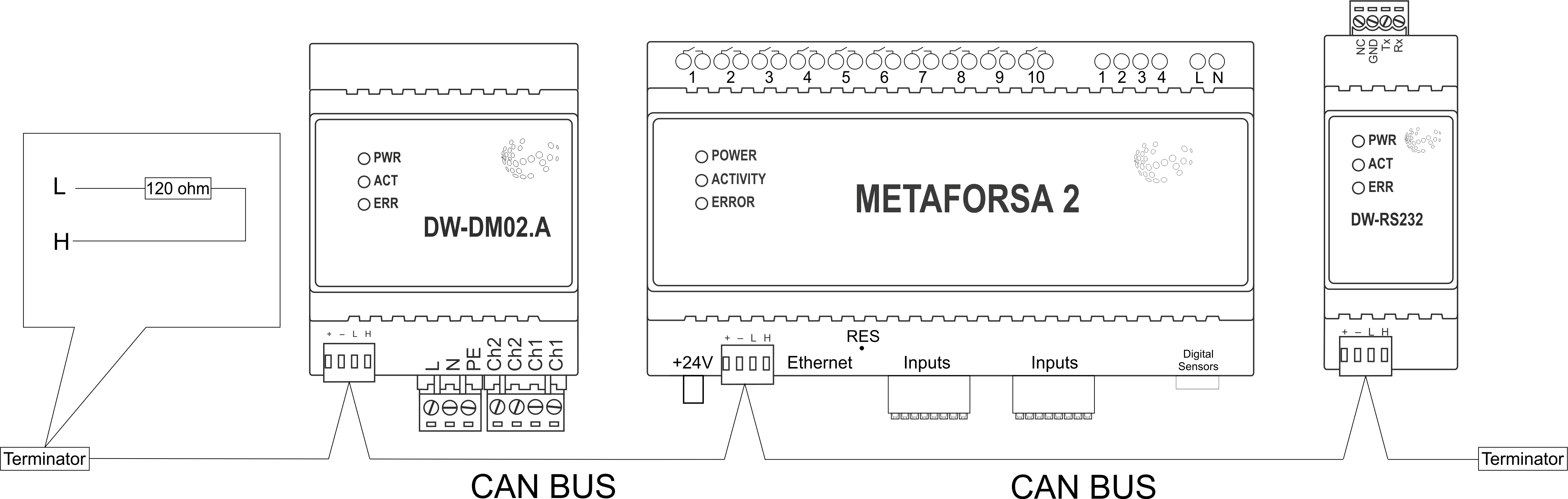
Expansion modules include Larnitech equipment connected through the CAN-bus. Such equipment includes: dimmers, RGB-backlit control modules, multimode sensors, etc. The equipment connected to the expansion port is defined automatically and does not require any preset tuning. Connector contact pin assignment is defined in Table 4. The example of connection is shown in Fig. 17.
|
| Caution! The 120 ohm terminating resistors should be installed at the end connectors between L and H contact points of CAN-bus. Ensure the connection is correct. The incorrect connection may cause sensor and/or module malfunction. |
Module installation and connection procedure
- Install the module in the switchboard on the DIN-rail and fix it with the special latch on the module base.
- Fasten the supply unit on the left side of the module.
- Connect the connector (4) having the noise filter pre-installed which is supplied complete with the module.
- Connect the connectors (5), (6).
- Connect the connectors (1), (2).
- Connect the connector (3).
- Apply power to the supply unit of METAFORSA module.
- Wait until the module is loaded, then configure it in accordance with the System Setup Instructions.
- Apply power to the connectors (1), (2).
- Check all equipment for proper operation.
METAFORSA module shut-off and deinstallation procedure
- De-energize the module by disconnecting the circuit breaker assembly of the load power supply and METAFORSA module supply unit. Verify the voltage is absent on the terminals (1), (2) of the connector wires and on the input terminals of the supply unit.
- Disconnect the load power supply connectors (1), (2).
- Disconnect the connector (3).
- Disconnect the connectors (4)-(6).
- Remove the module from the DIN-rail, releasing the latch at the bottom of the module base.
Hardware setup
To configure and control METAFORSA SMART HOUSE, you must install Larnitech software on your smartphone or tablet, which is available in App Store and Play Market. After installation, follow the System Setup Instructions.
Fault diagnostics and handling
The following are some possible faults and ways of fault handling. If you have any difficulty, or face the fault undeclared here, please contact the Technical Support: [1] or [support@larnitech.com]. There are also some tips in the FAQ section at our website [2].
The actuators do not operate:
- ensure the outputs are properly configured in the application (see System Setup Instructions);
- check the connection is correct in accordance with table 2 and paragraph 3.6;
- ensure the power is supplied to the input power contact , i.e. all circuit breaker assembly are ON.
- verify the operability of the connected equipment.
The module is off, indication absent:
- check the connection to 24V supply unit as shown in table 2 (contacts pin assignment);
- check the connection of the supply unit to 220V power mains, the indicator should be ON.
Network connection fault:
- ensure the Ethernet cable is properly wired and connected to the connector;
- ensure the LED status indicators are ON on the Ethernet connector;
- check the LAN configuration is correct, Ethernet cable loops are absent;
- METAFORSA module and the device you are connecting from are in the same network.
hold integer 0-10000 1-10 by default hold is the same as runtime hold is the bridging time in miliseconds, is used for gate and jalousie, lock; Example: hold=3500
The sensors do not operate:
- ensure the inputs are properly configured in the application (System Setup Instructions);
- check the connection is correct in accordance with table 2 and paragraph 3.7;
- ensure the METAFORSA module is ON: circuit breaker assembly is closed, indication on the supply unit is ON, the module indication corresponds to the operating status – table 3;
- check the power supply availability on the sensors;
- check the integrity of lines laid to the sensors.
The auxiliary equipment does not operate:
- check the connection is correct in accordance with table 2 and paragraph 3.8-9;
- ensure the METAFORSA module is ON: circuit breaker assembly is closed, indication on the supply unit is ON, the module indication corresponds to the operating status – table 3;
- check the integrity of the CAN lines, voltage supply on the modules.
HW Settings
| Name | Type, range | SUBID | Default | Description |
|---|---|---|---|---|
| runtime | integer 0-100 | 1-10 | 15 | runtime is the open/close time in seconds, is used for jalousie, gate, valve(2 pole);
|
| runtimeopen | integer 0-60000 | Blinds subId | Runtimeopen is the open time in milliseconds, is used for blinds; Example: runtimeopen=15000 | |
| runtimeclose | integer 0-60000 | Blinds subId | Runtimeclose is the close time in milliseconds, is used for blinds; Example: runtimeclose=15000 | |
| hold | integer 0-10000 | 1-10 | 500 | hold is the bridging time in milliseconds, is used for gate and jalousie (by default hold is the same as runtime for jalousie and gate), lock; Example: hold=3500 |
| def | string 'ON' | 1-10 | 'OFF' | def is the element status is set after restart, is used for lamp, heating, valve(1 pole); Example: def='ON' |
| stop | Char ‘R’ | 1-7 | – | (for 2-pole gate and blinds) If it is declared then by Stop command during the motion, the same impulse appears as it was at the beginning of the motion. Pole, an which the stop-impules is formed, is defined by the parameter Stop value. If it is ‘r’ or ‘R’ then stop-impulse is produced on the opposite to the start-impulse pole. If any other value is delcared (e.g., ‘d’ ) then the stop-impulse is on the same pole. If a Runtime passed after the beginning of the motion then the stop-impulse is not formed. Example: stop=’r’ |
| out | char[10] | 98 | 'LLLLHHHHP-' | Each char is responsible for the type of a particular channel
Example: out='LLB-G-V-W-' |
| dm | char[4] | 98 | ‘LLLL’ | Each char is responsible for the type of a particular channel
Example: dm=’skl-‘ |
| def | integer 0-250 | 11-14 | 100 | The default brightness level in case of a power reset (1..250). Example: def=250 |
| min | integer 0-100 | 11-14 | 0 | Minimum dimming level, example: min=10 |
| max | integer 0-100 | 11-14 | 100 | Maximum dimming level, example max=95 |
| start | integer 0-100 | 11-14 | 0 | The Start function is used for lamps that lack the minimal voltage to get turned on. If the set value is lower than the start value, the lamp is turned on at the start value and them the light is dimmed down to the set level. Example: start=60 |
| force | integer 0-100 | 11-14 | 10 | Time duration of the starting value (measured in milliseconds). Example: force=20 |
| runtime | integer 0-60000 | 11-14 | 1000 | Runtime is the speed of changing the brightness from ‘min’ to ‘max’ (measured in milliseconds). Example: runtime=1000 |
| offset | integer (+/- 0…39) | 39-46 | '0' | sensor values offset; For example, offset is -3.8 :
Example: hw="offset='-3.8'" |
| in | char[24] | 98 | 'BBBBBBBBBBBBMMMLLLKKKKKK' | Each char is responsible for the type of a particular channel
Example: in='MMMMMMMMMMMMLLLLLLLLLLLL' 12 motion sensors and 12 leak-sensors; in='BBBBBBBBSSSSSSBBBBSSSSSS' 12 buttons; 12 switches. |
 1<item addr="339:1" auto-period="600" cfgid="40" hw="def='ON'" name="Lamp" type="lamp" uniq_id="3779">
 2<item addr="339:2" cfgid="40" hw="def='ON'" name="Radiator" type="valve-heating" uniq_id="3780">
 3    <automation name="Eco" temperature-level="16" uniq_id="3781"/>
 4    <automation name="Comfort" temperature-level="22" uniq_id="3782"/>
 5    <automation name="Hot" temperature-level="25" uniq_id="3783"/>
 6</item>
 7<item addr="339:3" cfgid="40" hw="runtime=9" name="Jalousie" sub-type="120" type="jalousie" uniq_id="32"/>
 8<item addr="339:5" cfgid="40" hw="runtime=13" name="Gate" sub-type="120" type="gate" uniq_id="3784"/>
 9<item addr="339:7" cfgid="40" hw="hold=4600" name="Gate" sub-type="120" type="gate" uniq_id="3785"/>
10<item addr="339:8" cfgid="40" hw="runtime=10" name="Valve" type="valve" uniq_id="3786"/>
11<item addr="339:11" cfgid="40" name="Motion" type="motion-sensor" uniq_id="17"/>
12<item addr="339:12" cfgid="40" name="Motion" type="motion-sensor" uniq_id="18"/>
13<item addr="339:13" cfgid="40" name="Motion" type="motion-sensor" uniq_id="19"/>
14<item addr="339:16" cfgid="40" name="Leak" type="leak-sensor" uniq_id="21"/>
15<item addr="339:17" cfgid="40" name="Leak" type="leak-sensor" uniq_id="41"/>
16<item addr="339:19" cfgid="40" name="Switch" type="switch" uniq_id="22"/>
17<item addr="339:20" cfgid="40" name="Switch" type="switch" uniq_id="23"/>
18<item addr="339:21" cfgid="40" name="Switch" type="switch" uniq_id="24"/>
19<item addr="339:22" cfgid="40" name="Switch" type="switch" uniq_id="25"/>
20<item addr="339:23" cfgid="40" name="Door" type="door-sensor" uniq_id="26"/>
21<item addr="339:24" cfgid="40" name="Door" type="door-sensor" uniq_id="27"/>
22<item addr="339:25" cfgid="40" name="Door" type="door-sensor" uniq_id="28"/>
23<item addr="339:26" cfgid="40" name="Door" type="door-sensor" uniq_id="29"/>
24<item addr="339:30" cfgid="40" name="Temperature" type="temperature-sensor" uniq_id="3772"/>
25<item addr="339:31" cfgid="40" name="Temperature" type="temperature-sensor" uniq_id="3773"/>
26<item addr="339:32" cfgid="40" name="Temperature" type="temperature-sensor" uniq_id="3774"/>
27<item addr="339:33" cfgid="40" hw="offset='-10.8'" name="Temperature" type="temperature-sensor" uniq_id="3775"/>
28<item addr="339:34" cfgid="40" hw="offset='25.1'" name="Temperature" type="temperature-sensor" uniq_id="3776"/>
29<item addr="339:35" cfgid="40" name="Temperature" type="temperature-sensor" uniq_id="3777"/>
30<item addr="339:36" cfgid="40" name="Temperature" type="temperature-sensor" uniq_id="3778"/>
31<item addr="339:98" cfgid="40" hw="out='LHB-G-XV--' in='MMM--LL-BBBBKKKK'" name="Temperature" system="yes" type="temperature-sensor" uniq_id="30"/>