Metaforsa2 MF-14
| MF-14 | |||||||||||||
|---|---|---|---|---|---|---|---|---|---|---|---|---|---|
 | |||||||||||||
| |||||||||||||
| |||||||||||||
| |||||||||||||
Εισαγωγή
Το εγχειρίδιο εγκατάστασης METAFORSA SMART HOUSE περιγράφει τη διαδικασία εγκατάστασης, συναρμολόγησης, λειτουργίας και ρύθμισής του. Κατά την εργασία με το σύστημα, πρέπει να συμμορφώνεστε αυστηρά με όλες τις απαιτήσεις που ορίζονται σε αυτό το εγχειρίδιο. Η μη συμμόρφωση μπορεί να οδηγήσει σε ζημιά στη συσκευή, αστοχία της, ηλεκτροπληξία, πυρκαγιά και άλλες επιπτώσεις. Ο κατασκευαστής διατηρεί το δικαίωμα να κάνει αλλαγές σε αυτό το εγχειρίδιο χωρίς προηγούμενη ειδοποίηση. Αυτό το εγχειρίδιο αποτελεί αναπόσπαστο μέρος του συστήματος και θα παραμείνει στον πελάτη τελικής χρήσης.
Χαρακτηριστικά
- Υποστήριξη 10 καθολικών εξόδων:
- Φώτα
- Βαλβίδες θέρμανσης NC/NO
- Περσίδες
- Πύλες 1 ή 2 πόλων
- 1 ή 2-πολικές βαλβίδες
- Κλειδαριές NC/NO
- Μονάδες fan coil
- 4 εξόδους μείωσης της φωτεινότητας
- 24 διακριτικές είσοδοι που υποστηρίζουν:
- Κουμπιά
- Διακόπτες
- διακόπτες καλαμιών
- Αισθητήρες διαρροής
- ανιχνευτές κίνησης
- 4 ψηφιακές είσοδοι για έως και 8 αισθητήρες θερμοκρασίας
- Θύρα επέκτασης
- Ρελέ με επαφές AgSnO2 με ονομαστική τιμή ρεύματος εισόδου 80A 20ms
- Σύνδεση cloud και έλεγχος όλων των συστημάτων του σπιτιού
- Φωνητικός έλεγχος (Siri, Alexa, Google Home)
- Ο κινητήρας Plugins επιτρέπει την επέκταση των δυνατοτήτων του συστήματος (π.χ. ενσωμάτωση με φώτα Satel, Philips Hue, IKEA)
- Η ασφάλεια έναντι μη εξουσιοδοτημένης εισβολής διασφαλίζεται με κρυπτογράφηση RSA/AES256
- Ειδοποιήσεις Push από το σύστημα στο τηλέφωνό σας (επίσης είναι δυνατή η λήψη μέσω μηνυμάτων Telegram και Viber)
- Ιστορικό (αποθηκεύονται δεδομένα μετρητή για 1 έτος)
- Plug and play (δυνατότητα γρήγορης και εύχρηστης επέκτασης του συστήματος)
- Τακτικές ενημερώσεις συστήματος
- Μεγάλη συνεχώς ενημερωμένη βάση δεδομένων σεναρίων για να καλύψει όλες τις ανάγκες σας
- Αυτόματα καθημερινά αντίγραφα ασφαλείας μέσω cloud με δυνατότητα επαναφοράς της αρχικής διαμόρφωσης
- Open API (που επιτρέπει την ενσωμάτωση της Larnitech σε άλλα συστήματα)
- Διαδραστική και φιλική προς το χρήστη διεπαφή Ιστού LT SETUP διαθέσιμη για προηγμένες ρυθμίσεις
- ΣΥΝΔΕΣΤΕ και ΠΑΙΞΤΕ
- Είναι ένα πλήρως έτοιμο προς εγκατάσταση κιτ συστήματος Smart Home
Απαιτήσεις ασφαλείας
Για να αποφευχθεί ο κίνδυνος πυρκαγιάς, ηλεκτροπληξίας, ζημιάς στο σύστημα ή/και τραυματισμού, η εγκατάσταση και η συναρμολόγηση του συστήματος πρέπει να εκτελούνται σύμφωνα με τις οδηγίες που αναφέρονται παρακάτω:
- Όλες οι εργασίες σύνδεσης πρέπει να εκτελούνται χωρίς ρεύμα.
- χρησιμοποιήστε κατάλληλα εργαλεία και προσωπική προστασία από ηλεκτροπληξία.
- μην χρησιμοποιείτε κατεστραμμένα καλώδια, καλώδια και συνδέσμους.
- αποφύγετε την αναδίπλωση των καλωδίων και των καλωδίων.
- μην τσιμπήσετε ή τσακίσετε τα καλώδια και τα καλώδια ασκώντας υπερβολική δύναμη. Διαφορετικά, οι εσωτερικοί αγωγοί του καλωδίου και των καλωδίων μπορεί να απογυμνωθούν ή να σπάσουν.
- Μην χρησιμοποιείτε την πρίζα με κακές επαφές για σύνδεση.
- μην υπερβαίνετε το όριο των παραμέτρων φορτίου που καθορίζεται σε αυτό το εγχειρίδιο.
- το τμήμα σύρματος των αγωγών τροφοδοσίας υπόκειται στις προδιαγραφές για όριο πυκνότητας ρεύματος, τύπο μόνωσης και υλικό σύρματος. Το ελαφρύ τμήμα μπορεί να προκαλέσει υπερθέρμανση του καλωδίου και πυρκαγιά.
Όταν εργάζεστε με το σύστημα μετά την παροχή τάσης ΠΟΤΕ:
- πραγματοποιήστε σύνδεση/αποσύνδεση των βυσμάτων.
- ανοιχτές μονάδες και αισθητήρες.
Διαμόρφωση συστήματος και σκοπός
Σκοπός του συστήματος
Το METAFORSA SMART HOUSE είναι μια έτοιμη λύση για την αυτοματοποίηση οικιστικών και επαγγελματικών χώρων, ξενοδοχειακών συγκροτημάτων που περιλαμβάνει τα πιο επιθυμητά χαρακτηριστικά του Smart House.
Η συσκευή διαθέτει 10 κανάλια ελέγχου, 4 κανάλια dimming, 24 εισερχόμενα κανάλια αισθητήρα και μια θύρα σύνδεσης ψηφιακού αισθητήρα.
| Οι καθολικές έξοδοι μπορούν να χρησιμοποιηθούν για τον έλεγχο: | Οι καθολικές είσοδοι σάς επιτρέπουν να συνδέσετε: |
|---|---|
| Φωτισμός | Κουμπιά / μονάδες μεταγωγής |
| Υποδοχές | Διακόπτες μαγνητικού καλαμιού |
| Ενδοδαπέδια θέρμανση | Αισθητήρες κίνησης |
| Ενεργοποιητές κουρτίνας/πύλης | Αισθητήρες διαρροής |
| Βαλβίδες παροχής νερού/θέρμανσης |
'Θύρα σύνδεσης ψηφιακών αισθητήρων
Η θύρα σύνδεσης ψηφιακών αισθητήρων σάς επιτρέπει να συνδέσετε μια ποικιλία ψηφιακών αισθητήρων, όπως αισθητήρες θερμοκρασίας, φως περιβάλλοντος, υγρασία και άλλα.
'Θύρα επέκτασης
Η θύρα επέκτασης σάς επιτρέπει να αναβαθμίσετε το σύστημα συνδέοντας βοηθητικό εξοπλισμό, όπως η ηλεκτρονική μονάδα ελέγχου για φωτισμό LED, ρύθμιση φωτεινότητας, συσκευές μέτρησης και άλλα στοιχεία.
Το πακέτο, το οποίο είναι πλήρως έτοιμο για εγκατάσταση, περιλαμβάνει το βασικό υλικό και λογισμικό.
Περιεχόμενα πακέτου
Το πακέτο συνοδεύεται στάνταρ με:
| Mainframe METAFORSA MF-14.А | 1 τεμ |
| Τροφοδοτικό MEANWELL DR-15-12 | 1 τεμ |
| Αισθητήρας κίνησης CW-MSD | 3 τεμ |
| Αισθητήρας διαρροής FW-WL.A | 2 τεμ |
| Στοιχείο ευαίσθητο στη θερμοκρασία FW-TS.A | 4 τεμ |
| Μαγνητικός διακόπτης καλαμιού (αισθητήρας θέσης παραθύρου/πόρτας) | 4 τεμ |
| Φίλτρο θορύβου καλωδίου Ethernet | 1 τεμ |
| Καλώδιο τροφοδοσίας | 1 τεμ |
Βασικές τεχνικές προδιαγραφές του Συστήματος
Οι βασικές προδιαγραφές και τα χαρακτηριστικά της μονάδας METAFORSA MF-14.A φαίνονται στον πίνακα 1
| Προδιαγραφές | Εννοια |
|---|---|
| 'Θύρες εξόδου | |
| Αριθμός εναλλασσόμενων καναλιών | 10 |
| Αριθμός αλλαγμένων ομάδων | 10 |
| Αριθμός καναλιών μείωσης φωτεινότητας | 4 |
| Τάση μεταγωγής | 0-250 V AC/DC |
| Φορτίο αιχμής (ένα κανάλι) | 16Α |
| Φορτίο αιχμής (συσκευή) | 160Α |
| Μέγιστο φορτίο ανά κανάλι μείωσης φωτεινότητας | 0,5A (110W στα 220V) |
| Τύπος ροοστάτη | MOSFET |
| Τύπος φορτίου Dimmer | R,C |
| Τύπος φωτισμού | χείλος εκφυγής |
| Τύπος σύνδεσης καλωδίου τροφοδοσίας | σύνδεσμος |
| Επιτρεπόμενο τμήμα του καλωδίου τροφοδοσίας για σύνδεση στην πρίζα: καλώδιο ενός αγωγού καλώδιο πολλαπλών αγωγών καλώδιο πολλαπλών αγωγών με μύτη |
0,5 … 4mm2 0,5 … 4mm2 0,5 … 2,5 mm2 |
| Θύρες εισόδου | |
| Αριθμός διακριτών εισόδων | 24 |
| Αριθμός ψηφιακών εισόδων | 4 |
| Μέγιστη ονομαστική τιμή ρεύματος στους συνδετήρες τάσης συνεχούς ρεύματος | 50 mA |
| 'Άλλα' | |
| Θερμοκρασία περιβάλλοντος λειτουργίας | 0 … +45°С |
| Θερμοκρασία αποθήκευσης/μεταφοράς | -20 … +60°С |
| Επιτρεπτή υγρασία | 0 … 95% (χωρίς συμπύκνωση) |
| Τροφοδοσία | 12 … 27,5 V DC 24V, 0,75A Συνιστάται |
| Μέγιστη ζήτηση | 0,5Α |
| Διαθέσιμες διεπαφές | Ethernet, CAN, OneWire |
| Τύπος λεωφορείου | CAN (4-σύρματα) |
| CAN (4-wire) | 800 m* (στριφτό ζευγάρι 5 γάτα) |
| Τύπος σύρματος CAN | FTP Cat 5E |
| Τύπος σύνδεσης CAN | σύνδεσμος |
| Μέγιστο μήκος ψηφιακής γραμμής | 30 μ |
| Τύπος καλωδίου ψηφιακής γραμμής | UTP/FTP Cat 5E |
| Μέγιστο μήκος LAN | 100 μ |
| Τύπος καλωδίου LAN | UTP/FTP Cat 5E |
| Τύπος σύνδεσης LAN | Σύνδεσμος RJ-45 |
| Προδιαγραφές διαστάσεων | 9U, 156x110x58 mm |
| Υλικό κελύφους | Πλαστικό ABS |
| Κάσα | IP40 |
| Τύπος εγκατάστασης εξοπλισμού | DIN-rail (EN 60715) |
| Βάρος | 400 γρ |
* – η εγκατάσταση πρόσθετων μονάδων τροφοδοσίας απαιτείται για μεγάλες γραμμές. το μέγιστο μήκος της γραμμής μπορεί να μειωθεί από διάφορους παράγοντες παρεμβολής
Γενική δομή του Συστήματος
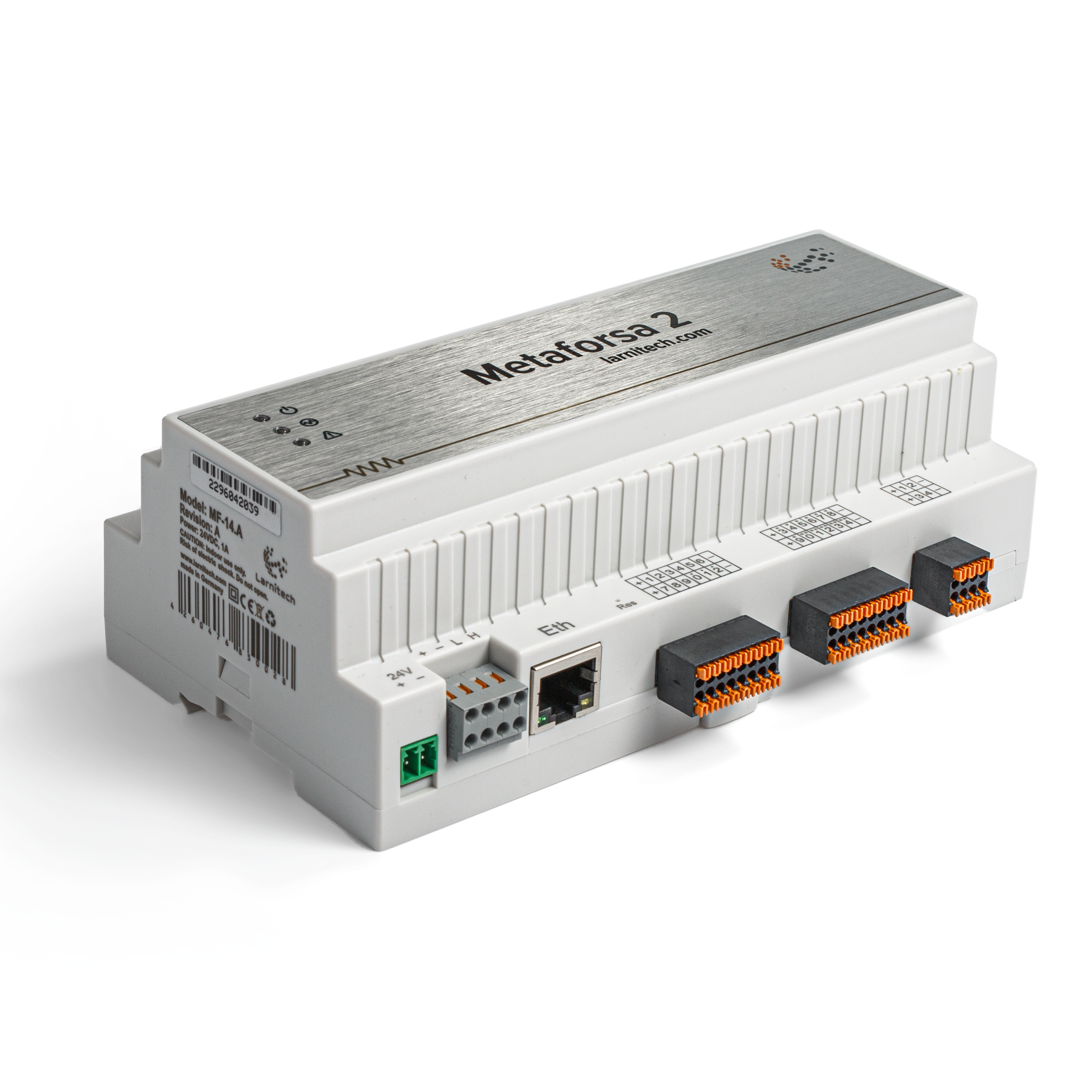
Η γενική όψη της μονάδας εμφανίζεται στο 'εικ. 1

| 1 | — σύνδεσμος για εφαρμογή φορτίου |
| 2 | — σύνδεσμος για εφαρμογή λαμπτήρων φωτισμού |
| 3 | — βύσμα τροφοδοσίας |
| 4 | — Υποδοχή δικτύου Ethernet |
| 5-6 | — υποδοχές για ψηφιακούς αισθητήρες και κουμπιά/μονάδες μεταγωγής |
| 7 | — Υποδοχή διασύνδεσης OneWire (για ψηφιακούς αισθητήρες) |
| 8 | — σύνδεσμος για μονάδα επέκτασης. |
Επισκόπηση των εξωτερικών βυσμάτων της συσκευής METAFORSA:
Στο επάνω μέρος του περιβλήματος ('εικ. 1') υπάρχει:
- υποδοχή (1) — Σύνδεση συσκευών.
- Βύσμα (2) — Σύνδεση λαμπτήρων μείωσης της έντασης του φωτός.
Στο κάτω μέρος του περιβλήματος ('εικ. 1') υπάρχει:
- βύσμα (3) — σύνδεση τροφοδοτικού μονάδας.
- σύνδεση (4) — Σύνδεση δικτύου Ethernet.
- βύσματα (5-6) — τέσσερις υποδοχές έξι σημείων για σύνδεση ψηφιακών αισθητήρων – αισθητήρες κίνησης, διαρροής, διακόπτη καλαμιού και *αισθητήρες κουμπιού/μονάδας μεταγωγής.
- υποδοχή (7) — Σύνδεση διαύλου ψηφιακών αισθητήρων OneWire.
- σύνδεσμος (8) — σύνδεση μονάδας επέκτασης.
Η φυσική διαμόρφωση και η αντιστοίχιση σημείων επαφής κάθε βύσματος φαίνονται στον πίνακας 2.
| Σύνδεσμος | Επικοινωνία | Ανάθεση |
|---|---|---|
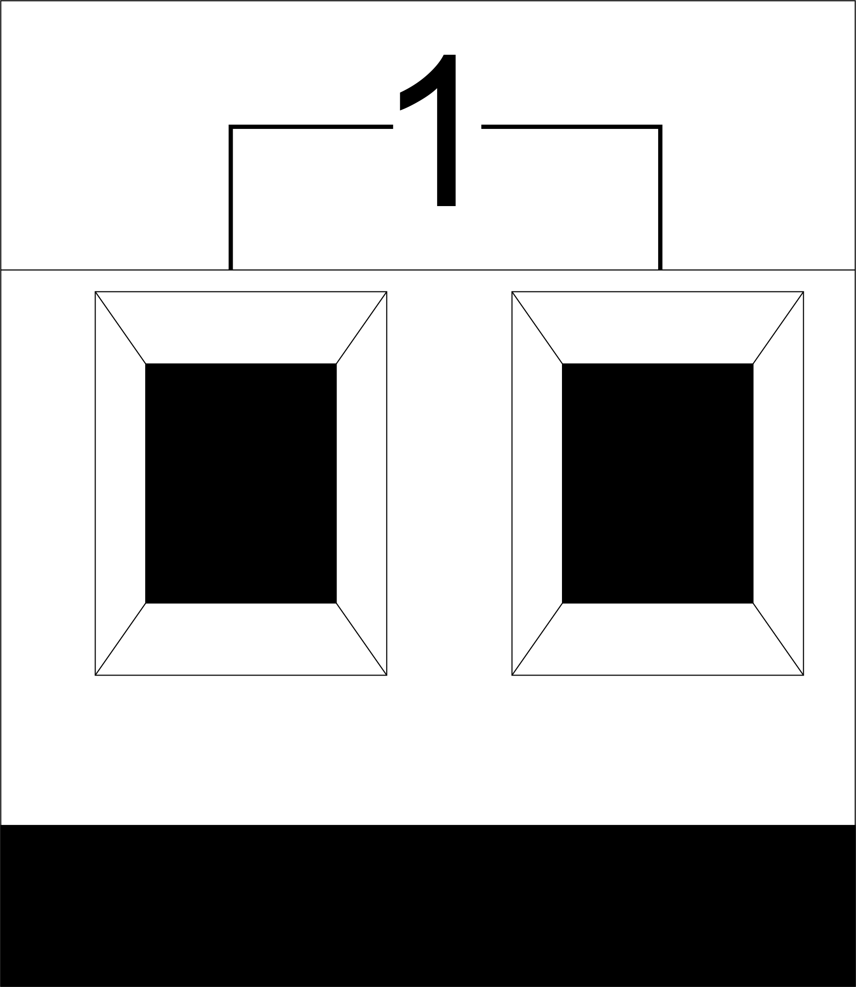 |
1-10 | Εφαρμογή φορτίου (λαμπτήρες φωτός, θερμικοί ενεργοποιητές κ.λπ.) |
| D1-4, L, N | Εφαρμογή φόρτωσης (λαμπτήρες φωτισμού) | |
| Ενδείξεις κατάστασης συσκευής | Οι δείκτες κατάστασης της μονάδας περιγράφονται στον πίνακα 3 | |
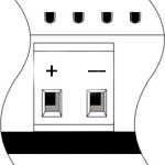 |
+24V GND |
+24V — τροφοδοσία μονάδας από εξωτερικό τροφοδοτικό 24 V GND — κοινό |
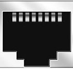 |
RJ45 | Υποδοχή για σύνδεση LAN |
| In1-12, In13-24 GND | Σύνδεση συσκευών ελέγχου (κουμπιά, μαγνητικοί διακόπτες καλαμιού, αισθητήρες κίνησης ή διαρροής): +12V — Έξοδος ισχύος αισθητήρα +12 V In1 … In24 — λογικές είσοδοι (0-12 V) GND — κοινές | |
 |
OneWire | Σύνδεση ψηφιακών αισθητήρων (θερμοκρασία) VCC — Έξοδος τροφοδοσίας αισθητήρων +5V OW1-OW4 — Διαύλους δεδομένων OneWire GND — κοινά |
 |
VCC GND L H |
Σύνδεση εξωτερικών μονάδων για CAN-bus VСС — Έξοδος 24V για εξωτερικές συσκευές τροφοδοτικό GND — συνηθισμένο L — Δίαυλος δεδομένων CAN-L H — Δίαυλος δεδομένων CAN-H |
| Indicator | Status | Description |
|---|---|---|
| Power | Power | |
| Power not available | ||
| Activity | Data communication | |
| Data communication not available | ||
| Error | No errors | |
| Communication error | ||
| Module overheat | ||
| Dimmer outputs module overload | ||
| Absence of power on dimmers, if in configuration |
Εγκατάσταση και συναρμολόγηση συστήματος
Πριν συνδέσετε το σύστημα, πρέπει:
- τοποθετήστε τον αισθητήρα και τους ενεργοποιητές (αν δεν είναι προεγκατεστημένοι), ρυθμίστε τους αισθητήρες και τους ενεργοποιητές.
- τοποθετήστε τη μονάδα και το τροφοδοτικό.
- το σήμα τον αισθητήρα και τους ενεργοποιητές (αν δεν είναι προεγκατεστημένοι), ρυθμίστε τους αισθητήρες και τους ενεργοποιητές.
- το αυτοκίνητο τη μονάδα και το τροφοδοτικό.
- Η ισχύς του συγκροτήματος διακόπτη κυκλώματος πρέπει να συμμορφώνεται με την ικανότητα φόρτωσης.
- Τίποτα άλλο εκτός από τους αγωγούς φάσης δεν μπορεί να συνδεθεί στη μονάδα, το ουδέτερο καλώδιο συνδέεται χωριστά.
Το τυπικό διάγραμμα της σύνδεσης μονάδας METAFORSA MF-14.A φαίνεται στο εικ. 3.'

Σύνδεση των ενεργοποιητών
Σύνδεση των φώτων/ηλεκτρικού επαφέα/θερμικού ενεργοποιητή θέρμανσης
 Εικ. 4 |
Τέτοιοι ενεργοποιητές όπως φως, ηλεκτρικός επαφέας, θερμικός ενεργοποιητής θέρμανσης θα πρέπει να ενεργοποιούνται σε οποιαδήποτε από τις εξόδους 1 – 10, το ουδέτερο καλώδιο και το καλώδιο γείωσης πρέπει να συνδέονται απευθείας στον πίνακα διανομής. Το παράδειγμα σύνδεσης φαίνεται στο Εικ.4. |
Σύνδεση συσκευής υψηλού φορτίου
 |
Προτεινόμενοι επαφές:
|
Connection of single-pole water/gas supply valve
| Caution: Before applying power to the load, make sure that the output configuration of METAFORSA module is correct. The incorrect configuration or incorrect connection can cause the module failure and/or failure of the equipment connected to it, and even a fire. | |
 Fig. 5 |
The single pole water/gas supply valve is connected to any of the outputs of 1 – 10, the (neutral wire and the ground wire are connected directly to the switchboard. The example of connection is shown in Fig.5. |
Connection of double-pole water/gas supply valve
| Caution: Before applying power to the valve, it is necessary to ensure the output configuration of METAFORSA module is correct. The incorrect configuration can cause the voltage application simultaneously to both channels of the valve, which may result in the module failure and/or failure of the equipment connected to it, and even a fire. | |
 Fig. 6 |
Two adjacent contact points (for example, 3, 4) are used to connect the double-pole water/gas supply valve; in these conditions the neutral wire and the ground wire are connected directly to the switchboard. The example of connection is shown in Fig.6. |
Connection of single-pole gate actuator
| Caution: Before applying power to the module, you should properly configure access to the application. The contacts incorrectly configured can result in the module failure and/or failure of the equipment connected to it, and even a fire.
| |
 Fig. 7 |
Any contact point (for example, 3) is used to connect the single-pole gate drive controllers. The example of connection is shown in Fig.7. |
Connection of double-pole gate actuator
| Caution: Before applying power to the module, you must properly configure the outputs in the application. The contacts configured incorrectly can lead to simultaneous power supply to both channels, resulting in the module failure and/or failure of the equipment connected to it, and even a fire.
| |
 Fig. 8 |
Two adjacent contact points (for example, 3, 4) should be used to connect the double-pole gate drive controller. The example of connection is shown in Fig.8. |
Connection of curtain/jalousie/shutter actuator with 220V force control
| Caution: Before applying power to the module, you must properly configure the outputs in the application. The contacts configured incorrectly can lead to simultaneous power supply to both channels, resulting in the module failure and/or failure of the equipment connected to it, and even a fire.
| |
 Fig. 9 |
Two adjacent contact points (for example, 3, 4) should be used to connect the curtain/jalousie/rolladens actuator, in these conditions the neutral wire and the ground wire are connected directly to the switchboard. The example of connection is shown in Fig.9. |
Connection of curtain/jalousie/shutter actuator with low-voltage control
| Caution: Before applying power to the module, you must properly configure the outputs in the application. The contacts configured incorrectly can lead to simultaneous power supply to both channels, resulting in the module failure and/or failure of the equipment connected to it, and even a fire.
| |
 Fig. 10 |
Two adjacent contact points (for example, 3, 4) should be used to connect the curtain/jalousie/rolladens actuator with low-voltage control. The example of connection is shown in Fig.10. |
Connection of sensing elements/switches/buttons
Connection of motion sensors
The motion sensors should be connected to any free input in1-in24; in these conditions their power is connected to the contact points of +12V and GND of the relevant group. The example of connection is shown in Fig.11.

Fig. 11
Connection of FW-WL.A leakage sensors
FW-WL.A leakage sensors are connected to any free input in1 – in24, in these conditions the power should be connected to +12V and GND points of the relevant group. The example of connection is shown in fig. 12.
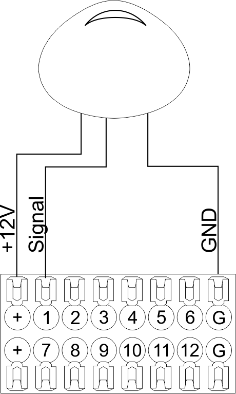 Fig12 |
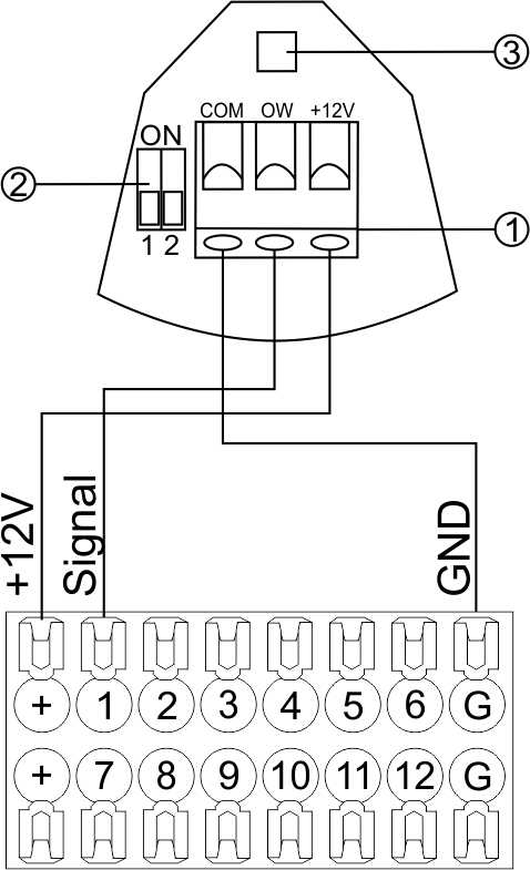 Fig13 |
Configuration and connection of the FW-WL.A sensor 1. Terminals:
- +12V — sensor power is connected to the contact point of METAFORSA “+12V”;
- OW — sensor pickup signal;
- GND — common, connected to GND contact of METAFORSA.
2. Sensor preset switch (optionally):
- 1 — sensor sensitivity (ON – high, OFF – low);
- 2 — indicator colour setting (ON – blue, OFF – green).
3. LED status indicator.
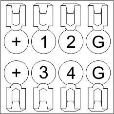
Connection of buttons/switches/magnetic reed switches
Buttons and reed switches are connected to any free input in1-in24, while their second contact point is connected to GND point of the relevant METAFORSA module group, + 12V power outputs – not in use. The example of connection is shown in Fig. 14-15.
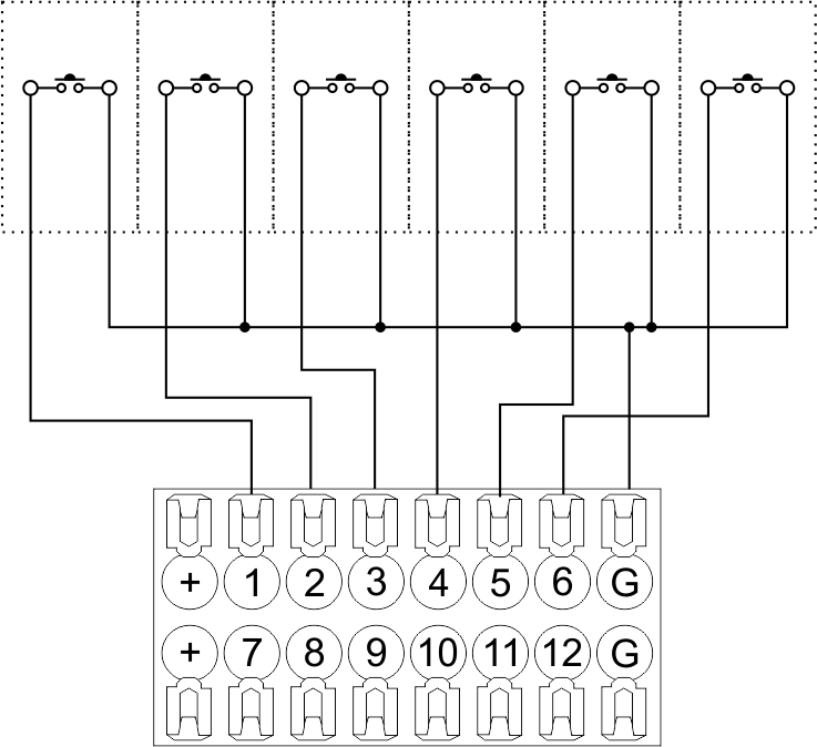 Fig14 connection of buttons/switching units |
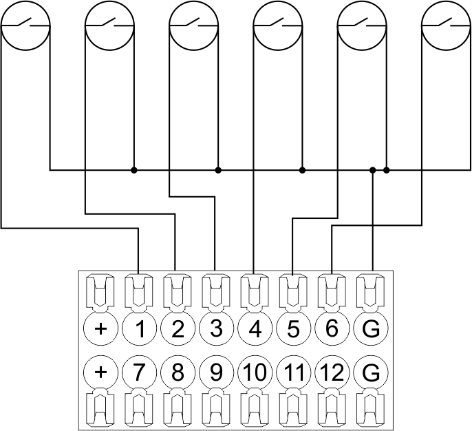 Fig15 connection of the magnetic reed switches (window/door position sensors) |
Connection of digital sensors
The OW adapter (Fig. 16a) is supplied along with METAFORSA module with the possibility to connect up to 8 digital sensors to it. In these conditions, several devices can be connected to one channel (Fig. 16b). The connected sensors are detected automatically and do not require any original setting.
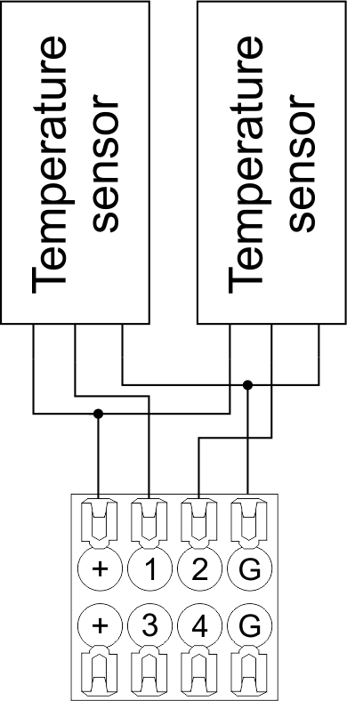 Fig16 a |
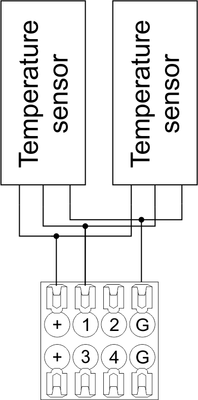 Fig16 b |
Configuration and connection of the OW adapter
Connection of auxiliary equipment.
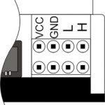
Expansion modules include Larnitech equipment connected through the CAN-bus. Such equipment includes: dimmers, RGB-backlit control modules, multimode sensors, etc. The equipment connected to the expansion port is defined automatically and does not require any preset tuning. Connector contact pin assignment is defined in Table 4. The example of connection is shown in Fig. 17.
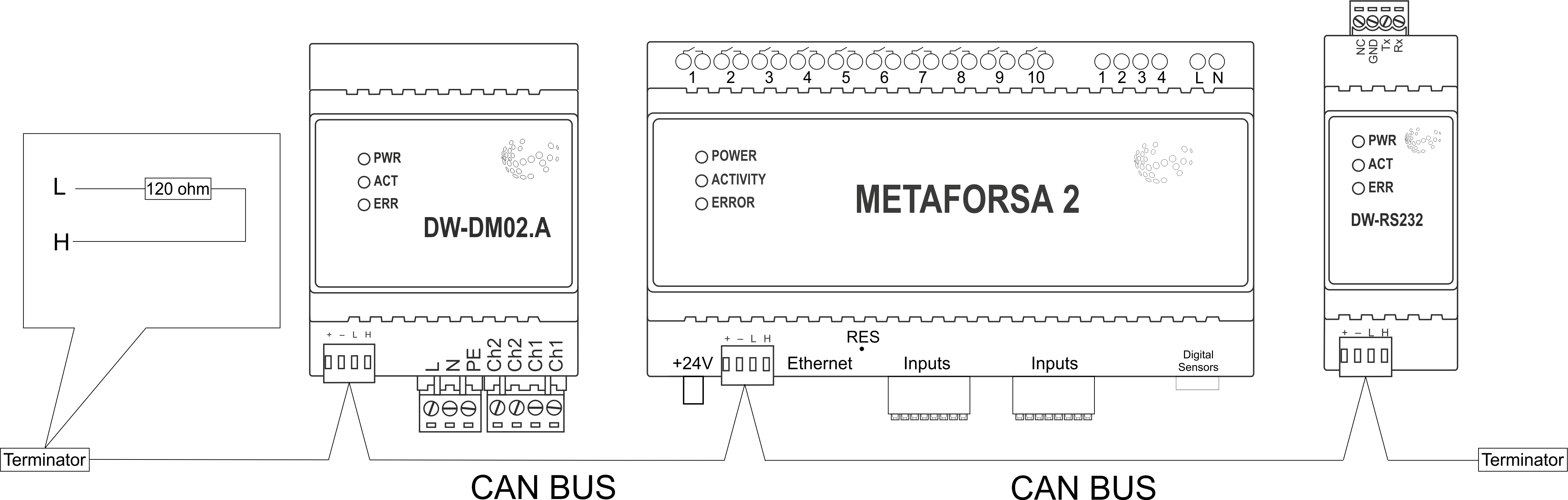
|
| Caution! The 120 ohm terminating resistors should be installed at the end connectors between L and H contact points of CAN-bus. Ensure the connection is correct. The incorrect connection may cause sensor and/or module malfunction. |
Module installation and connection procedure
- Install the module in the switchboard on the DIN-rail and fix it with the special latch on the module base.
- Fasten the supply unit on the left side of the module.
- Connect the connector (4) having the noise filter pre-installed which is supplied complete with the module.
- Connect the connectors (5), (6).
- Connect the connectors (1), (2).
- Connect the connector (3).
- Apply power to the supply unit of METAFORSA module.
- Wait until the module is loaded, then configure it in accordance with the System Setup Instructions.
- Apply power to the connectors (1), (2).
- Check all equipment for proper operation.
METAFORSA module shut-off and deinstallation procedure
- De-energize the module by disconnecting the circuit breaker assembly of the load power supply and METAFORSA module supply unit. Verify the voltage is absent on the terminals (1), (2) of the connector wires and on the input terminals of the supply unit.
- Disconnect the load power supply connectors (1), (2).
- Disconnect the connector (3).
- Disconnect the connectors (4)-(6).
- Remove the module from the DIN-rail, releasing the latch at the bottom of the module base.
Hardware setup
To configure and control METAFORSA SMART HOUSE, you must install Larnitech software on your smartphone or tablet, which is available in App Store and Play Market. After installation, follow the System Setup Instructions.
Fault diagnostics and handling
The following are some possible faults and ways of fault handling. If you have any difficulty, or face the fault undeclared here, please contact the Technical Support: [1] or [support@larnitech.com]. There are also some tips in the FAQ section at our website [2].
The actuators do not operate:
- ensure the outputs are properly configured in the application (see System Setup Instructions);
- check the connection is correct in accordance with table 2 and paragraph 3.6;
- ensure the power is supplied to the input power contact , i.e. all circuit breaker assembly are ON.
- verify the operability of the connected equipment.
The module is off, indication absent:
- check the connection to 24V supply unit as shown in table 2 (contacts pin assignment);
- check the connection of the supply unit to 220V power mains, the indicator should be ON.
Network connection fault:
- ensure the Ethernet cable is properly wired and connected to the connector;
- ensure the LED status indicators are ON on the Ethernet connector;
- check the LAN configuration is correct, Ethernet cable loops are absent;
- METAFORSA module and the device you are connecting from are in the same network.
hold integer 0-10000 1-10 by default hold is the same as runtime hold is the bridging time in miliseconds, is used for gate and jalousie, lock; Example: hold=3500
The sensors do not operate:
- ensure the inputs are properly configured in the application (System Setup Instructions);
- check the connection is correct in accordance with table 2 and paragraph 3.7;
- ensure the METAFORSA module is ON: circuit breaker assembly is closed, indication on the supply unit is ON, the module indication corresponds to the operating status – table 3;
- check the power supply availability on the sensors;
- check the integrity of lines laid to the sensors.
The auxiliary equipment does not operate:
- check the connection is correct in accordance with table 2 and paragraph 3.8-9;
- ensure the METAFORSA module is ON: circuit breaker assembly is closed, indication on the supply unit is ON, the module indication corresponds to the operating status – table 3;
- check the integrity of the CAN lines, voltage supply on the modules.
HW Settings
| Name | Type, range | SUBID | Default | Description |
|---|---|---|---|---|
| runtime | integer 0-100 | 1-10 | 15 | runtime is the open/close time in seconds, is used for jalousie, gate, valve(2 pole);
|
| runtimeopen | integer 0-60000 | Blinds subId | Runtimeopen is the open time in milliseconds, is used for blinds; Example: runtimeopen=15000 | |
| runtimeclose | integer 0-60000 | Blinds subId | Runtimeclose is the close time in milliseconds, is used for blinds; Example: runtimeclose=15000 | |
| hold | integer 0-10000 | 1-10 | 500 | hold is the bridging time in milliseconds, is used for gate and jalousie (by default hold is the same as runtime for jalousie and gate), lock; Example: hold=3500 |
| def | string 'ON' | 1-10 | 'OFF' | def is the element status is set after restart, is used for lamp, heating, valve(1 pole); Example: def='ON' |
| stop | Char ‘R’ | 1-7 | – | (for 2-pole gate and blinds) If it is declared then by Stop command during the motion, the same impulse appears as it was at the beginning of the motion. Pole, an which the stop-impules is formed, is defined by the parameter Stop value. If it is ‘r’ or ‘R’ then stop-impulse is produced on the opposite to the start-impulse pole. If any other value is delcared (e.g., ‘d’ ) then the stop-impulse is on the same pole. If a Runtime passed after the beginning of the motion then the stop-impulse is not formed. Example: stop=’r’ |
| out | char[10] | 98 | 'LLLLHHHHP-' | Each char is responsible for the type of a particular channel
Example: out='LLB-G-V-W-' |
| dm | char[4] | 98 | ‘LLLL’ | Each char is responsible for the type of a particular channel
Example: dm=’skl-‘ |
| def | integer 0-250 | 11-14 | 100 | The default brightness level in case of a power reset (1..250). Example: def=250 |
| min | integer 0-100 | 11-14 | 0 | Minimum dimming level, example: min=10 |
| max | integer 0-100 | 11-14 | 100 | Maximum dimming level, example max=95 |
| start | integer 0-100 | 11-14 | 0 | The Start function is used for lamps that lack the minimal voltage to get turned on. If the set value is lower than the start value, the lamp is turned on at the start value and them the light is dimmed down to the set level. Example: start=60 |
| force | integer 0-100 | 11-14 | 10 | Time duration of the starting value (measured in milliseconds). Example: force=20 |
| runtime | integer 0-60000 | 11-14 | 1000 | Runtime is the speed of changing the brightness from ‘min’ to ‘max’ (measured in milliseconds). Example: runtime=1000 |
| offset | integer (+/- 0…39) | 39-46 | '0' | sensor values offset; For example, offset is -3.8 :
Example: hw="offset='-3.8'" |
| in | char[24] | 98 | 'BBBBBBBBBBBBMMMLLLKKKKKK' | Each char is responsible for the type of a particular channel
Example: in='MMMMMMMMMMMMLLLLLLLLLLLL' 12 motion sensors and 12 leak-sensors; in='BBBBBBBBSSSSSSBBBBSSSSSS' 12 buttons; 12 switches. |
 1<item addr="339:1" auto-period="600" cfgid="40" hw="def='ON'" name="Lamp" type="lamp" uniq_id="3779">
 2<item addr="339:2" cfgid="40" hw="def='ON'" name="Radiator" type="valve-heating" uniq_id="3780">
 3    <automation name="Eco" temperature-level="16" uniq_id="3781"/>
 4    <automation name="Comfort" temperature-level="22" uniq_id="3782"/>
 5    <automation name="Hot" temperature-level="25" uniq_id="3783"/>
 6</item>
 7<item addr="339:3" cfgid="40" hw="runtime=9" name="Jalousie" sub-type="120" type="jalousie" uniq_id="32"/>
 8<item addr="339:5" cfgid="40" hw="runtime=13" name="Gate" sub-type="120" type="gate" uniq_id="3784"/>
 9<item addr="339:7" cfgid="40" hw="hold=4600" name="Gate" sub-type="120" type="gate" uniq_id="3785"/>
10<item addr="339:8" cfgid="40" hw="runtime=10" name="Valve" type="valve" uniq_id="3786"/>
11<item addr="339:11" cfgid="40" name="Motion" type="motion-sensor" uniq_id="17"/>
12<item addr="339:12" cfgid="40" name="Motion" type="motion-sensor" uniq_id="18"/>
13<item addr="339:13" cfgid="40" name="Motion" type="motion-sensor" uniq_id="19"/>
14<item addr="339:16" cfgid="40" name="Leak" type="leak-sensor" uniq_id="21"/>
15<item addr="339:17" cfgid="40" name="Leak" type="leak-sensor" uniq_id="41"/>
16<item addr="339:19" cfgid="40" name="Switch" type="switch" uniq_id="22"/>
17<item addr="339:20" cfgid="40" name="Switch" type="switch" uniq_id="23"/>
18<item addr="339:21" cfgid="40" name="Switch" type="switch" uniq_id="24"/>
19<item addr="339:22" cfgid="40" name="Switch" type="switch" uniq_id="25"/>
20<item addr="339:23" cfgid="40" name="Door" type="door-sensor" uniq_id="26"/>
21<item addr="339:24" cfgid="40" name="Door" type="door-sensor" uniq_id="27"/>
22<item addr="339:25" cfgid="40" name="Door" type="door-sensor" uniq_id="28"/>
23<item addr="339:26" cfgid="40" name="Door" type="door-sensor" uniq_id="29"/>
24<item addr="339:30" cfgid="40" name="Temperature" type="temperature-sensor" uniq_id="3772"/>
25<item addr="339:31" cfgid="40" name="Temperature" type="temperature-sensor" uniq_id="3773"/>
26<item addr="339:32" cfgid="40" name="Temperature" type="temperature-sensor" uniq_id="3774"/>
27<item addr="339:33" cfgid="40" hw="offset='-10.8'" name="Temperature" type="temperature-sensor" uniq_id="3775"/>
28<item addr="339:34" cfgid="40" hw="offset='25.1'" name="Temperature" type="temperature-sensor" uniq_id="3776"/>
29<item addr="339:35" cfgid="40" name="Temperature" type="temperature-sensor" uniq_id="3777"/>
30<item addr="339:36" cfgid="40" name="Temperature" type="temperature-sensor" uniq_id="3778"/>
31<item addr="339:98" cfgid="40" hw="out='LHB-G-XV--' in='MMM--LL-BBBBKKKK'" name="Temperature" system="yes" type="temperature-sensor" uniq_id="30"/>