Metaforsa2 MF-14
| MF-14 | |||||||||||||
|---|---|---|---|---|---|---|---|---|---|---|---|---|---|
 | |||||||||||||
| |||||||||||||
| |||||||||||||
| |||||||||||||
Bevezetés
A METAFORSA SMART HOUSE telepítési kézikönyve leírja a telepítési, összeszerelési, működési és beállítási eljárást. A rendszerrel végzett munka során szigorúan be kell tartania a jelen kézikönyvben meghatározott összes követelményt. Ennek be nem tartása a készülék károsodását, meghibásodását, áramütést, tüzet és egyéb kiesést okozhat. A gyártó fenntartja a jogot, hogy előzetes értesítés nélkül módosítsa ezt a kézikönyvet. Ez a kézikönyv a rendszer szerves részét képezi, és a végfelhasználónál marad.
Jellemzők
- 10 univerzális kimenet támogatása:
- Lámpák
- NC/NO fűtőszelepek
- Rolák
- 1 vagy 2 pólusú kapuk
- 1 vagy 2 pólusú szelepek
- NC/NO zárak
- Fan coil egységek
- 4 fényerő-szabályzó kimenet
- 24 diszkrét bemenet, amely támogatja:
- Gombok
- Kapcsolók
- reed kapcsolók
- szivárgásérzékelők
- mozgásérzékelők
- 4 digitális bemenet akár 8 hőmérséklet-érzékelőhöz
- Hosszabbító port
- AgSnO2 érintkezőkkel ellátott relék 80A 20ms bekapcsolási áramra
- Felhőcsatlakozás és az összes házrendszer vezérlése
- Hangvezérlés (Siri, Alexa, Google Home)
- A Plugins motor lehetővé teszi a rendszerlehetőségek bővítését (pl. integrálása Satel, Philips Hue, IKEA lámpákkal)
- Az RSA/AES256 titkosítás biztosítja a jogosulatlan behatolás elleni védelmet
- Push értesítések a rendszertől a telefonon (a Telegram és a Viber messengereken keresztül is fogadható)
- Előzmények (a mérőadatokat 1 évre tároljuk)
- Plug and play (lehetőség a rendszer gyors és felhasználóbarát bővítésére)
- Rendszeres rendszerfrissítések
- A szkriptek nagy, folyamatosan frissített adatbázisa minden igényt kielégít
- Automatikus napi biztonsági mentés felhőn keresztül, a kezdeti konfiguráció visszaállításának lehetőségével
- Nyitott API (amely lehetővé teszi a Larnitech integrálását más rendszerekbe)
- Interaktív és felhasználóbarát LT SETUP webes felület áll rendelkezésre a speciális konfigurációhoz
- Plug and Play
- Ez egy teljesen telepítésre kész Smart Home rendszerkészlet
Biztonsági követelmények
A tűz, áramütés, rendszerkárosodás és/vagy személyi sérülés elkerülése érdekében a rendszer telepítését és összeszerelését az alábbi utasítások szerint kell elvégezni:
- minden csatlakozási munkát áram nélkül kell elvégezni;
- használjon megfelelő szerszámokat és személyi védelmet az áramütés ellen;
- ne használjon sérült kábeleket, vezetékeket és csatlakozókat;
- kerülje a kábelek és vezetékek összehajtását;
- ne csípje be vagy törje meg a kábeleket és vezetékeket túlzott erővel. Ellenkező esetben a kábel és a vezetékek belső vezetői lecsupaszodhatnak vagy eltörhetnek;
- ne használja a gyenge érintkezőkkel rendelkező konnektort a csatlakoztatáshoz;
- ne lépje túl a terhelési paraméterek ebben a kézikönyvben meghatározott határértékét;
- a tápvezetékek vezetékszakaszára az áramsűrűség határértékre, a szigetelés típusára és a vezeték anyagára vonatkozó előírások vonatkoznak. A könnyű szakasz a kábel túlmelegedését és tüzet okozhat.
Ha a rendszerrel SOHA feszültségellátás után dolgozik:
- csatlakozók csatlakoztatása/leválasztása;
- nyitott modulok és érzékelők.
Rendszerkonfiguráció és cél
A rendszer célja
A METAFORSA SMART HOUSE egy kész megoldás lakó- és kereskedelmi helyiségek, szállodakomplexumok automatizálására, amely tartalmazza a Smart House legkívánatosabb tulajdonságait.
A készülék 10 vezérlőcsatornával, 4 fényerőszabályzó csatornával, 24 bejövő szenzorcsatornával és digitális érzékelők csatlakozási portjával rendelkezik.
| Univerzális kimenetekkel vezérelhető: | Az univerzális bemenetek lehetővé teszik a következők csatlakoztatását: |
|---|---|
| Világítás | Gombok/kapcsoló egységek |
| Aljzatcsatlakozók | Mágneses reed kapcsolók |
| Padlófűtés | Mágneses reed kapcsolók |
| Függöny/kapu működtető szerkezetek | Szivárgásérzékelők |
| Vízellátó/fűtő szelepek |
Digitális érzékelők csatlakozási portja
A digitális érzékelők csatlakozóportja lehetővé teszi számos digitális érzékelő csatlakoztatását, például hőmérséklet-, környezeti fény-, páratartalom- és egyéb érzékelők csatlakoztatását.
Bővítő port
A bővítőport lehetővé teszi a rendszer frissítését olyan segédberendezések csatlakoztatásával, mint például a LED-világítás vezérlőmodulja, fényerőszabályzó, mérőeszközök és egyéb elemek.
A teljesen telepítésre kész csomag tartalmazza az alapvető hardvert és szoftvert.
Csomag tartalma
A csomag alapfelszereltsége:
| Mainframe METAFORSA MF-14.А | 1 db |
| Tápegység MEANWELL DR-15-12 | 1 db |
| Mozgásérzékelő CW-MSD | 3 db |
| Szivárgásérzékelő FW-WL.A | 2 db |
| Hőmérséklet-érzékeny elem FW-TS.A | 4 db |
| Mágneses reed kapcsoló (ablak/ajtó helyzetérzékelő) | 4 db |
| Ethernet-kábel zajszűrő | 1 db |
| Tápkábel | 1 db |
A rendszer alapvető műszaki adatai
A METAFORSA MF-14.A modul alapvető műszaki adatai és jellemzői az 1. táblázatban láthatók.
| Leírás | Jelentése |
|---|---|
| 'Kimeneti portok | |
| A kapcsolt csatornák száma | 10 |
| Átkapcsolt csoportok száma | 10 |
| Tompító csatornák száma | 4 |
| Kommutációs feszültség | 0-250 V AC/DC |
| Csúcsterhelés (egy csatorna) | 16A |
| Csúcsterhelés (eszköz) | 160A |
| Maximális terhelés tompító csatornánként | 0,5 A (110 W 220 V-on) |
| Dimmer típus | MOSFET |
| Dimmer terhelés típusa | R,C |
| Tompítás típusa | kilépőél |
| Tápkábel csatlakozási típusa | csatlakozó |
| Az aljzatba csatlakoztatható tápkábel megengedett szakasza: egyvezetős kábel többvezetős kábel véges többvezetős kábel |
0,5 … 4mm2 0,5 … 4mm2 0,5 … 2,5 mm2 |
| Bemeneti portok | |
| Diszkrét bemenetek száma | 24 |
| Digitális bemenetek száma | 4 |
| Maximális névleges áramerősség az egyenáramú feszültségcsatlakozókon | 50mA |
| Egyéb | |
| Működési környezeti hőmérséklet | 0 … +45°С |
| Tárolási/szállítási hőmérséklet | -20 … +60°С |
| Megengedett páratartalom | 0…95% (nem lecsapódó) |
| Tápegység | 12 … 27,5 V DC 24 V, 0,75 A ajánlott |
| Maximális kereslet | 0,5А |
| Elérhető interfészek | Ethernet, CAN, OneWire |
| Busztípus | CAN (4 vezetékes) |
| CAN (4 vezetékes) | 800 m* (csavart érpár 5 kat) |
| CAN vezetéktípus | FTP Cat 5E |
| CAN csatlakozás típusa | csatlakozó |
| Digitális vonal maximális hossza | 30 m |
| Digitális vonali vezeték típusa | UTP/FTP Cat 5E |
| LAN maximális hossza | 100 m |
| LAN vezeték típusa | UTP/FTP Cat 5E |
| LAN kapcsolat típusa | RJ-45 csatlakozó |
| Méretadatok | 9U, 156x110x58 mm |
| Héjanyag | ABS műanyag |
| Borok | IP40 |
| Berendezés beépítési típusa | DIN-sín (EN 60715) |
| Súly | 400 g |
* – hosszú vezetékekhez további tápegységek telepítése szükséges; a vonal maximális hosszát különböző zavaró tényezők csökkenthetik
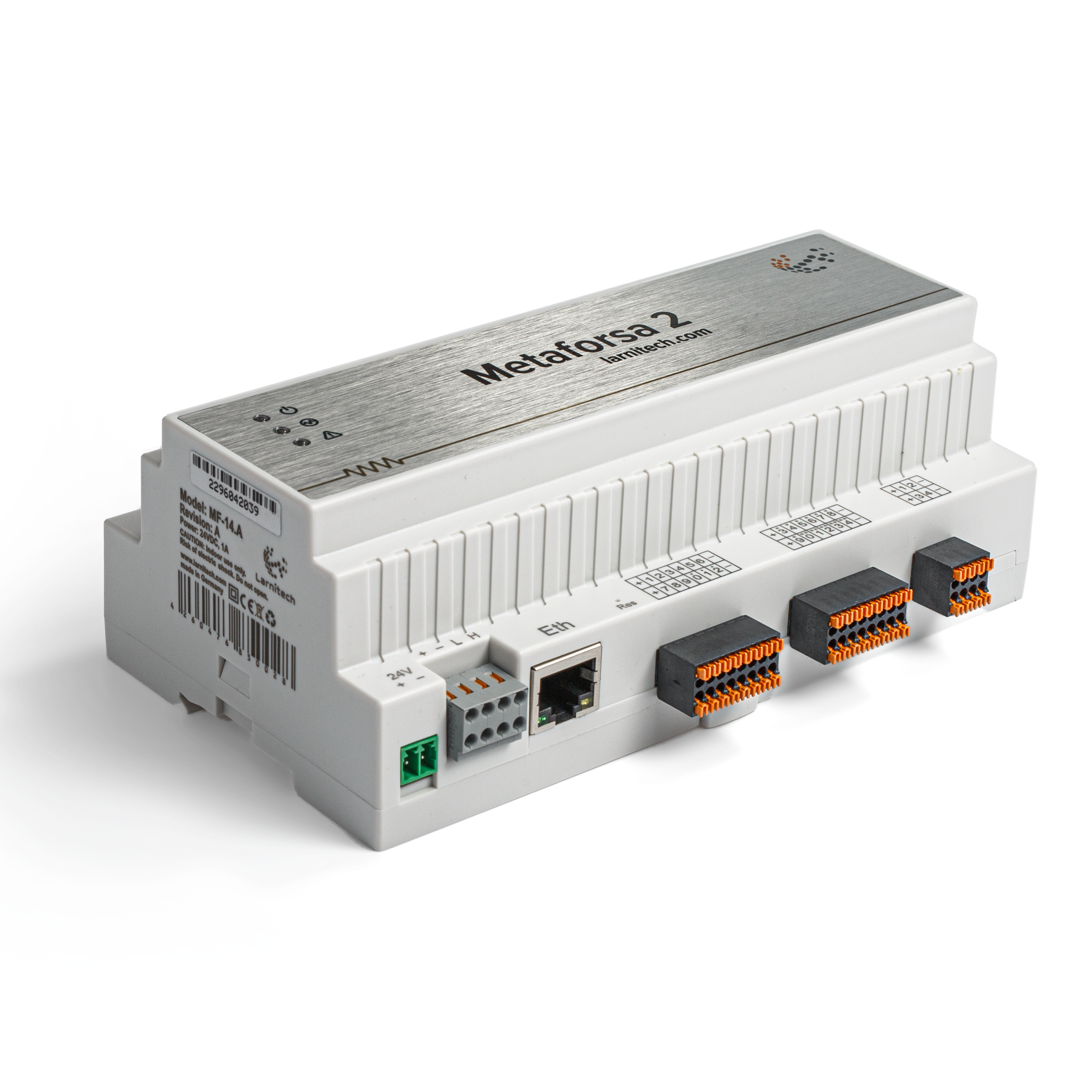
A rendszer általános felépítése
A modul általános nézete a ábrán látható. 1

| 1 | — csatlakozó terhelés alkalmazásához |
| 2 | — csatlakozó tompító lámpákhoz |
| 3 | - konnektor |
| 4 | — Ethernet hálózati csatlakozó |
| 5-6 | — digitális érzékelők és gombok/kapcsolóegységek csatlakozói |
| 7 | — OneWire interfész csatlakozó (digitális érzékelőkhöz) |
| 8 | — csatlakozó a bővítőmodulhoz. |
'A METAFORSA eszköz külső csatlakozóinak áttekintése:
A ház tetején (1. ábra) található:
- csatlakozó (1) — Eszközök csatlakoztatása;
- csatlakozó (2) — Tompító lámpák csatlakozása;
A ház alján (1. ábra) található:
- csatlakozó (3) — modul tápcsatlakozása;
- csatlakozó (4) — Ethernet hálózati csatlakozás;
- csatlakozók (5-6) – négy hatpontos csatlakozó digitális érzékelők csatlakoztatásához – mozgás-, szivárgás-, reed-kapcsoló-érzékelők és *gomb-/kapcsolóegység-érzékelők;
- csatlakozó (7) — OneWire digitális érzékelők buszcsatlakozása;
- csatlakozó (8) — bővítőmodul csatlakozás.
Az egyes csatlakozók fizikai konfigurációja és érintkezési pontjai a 2. táblázatban láthatók.
| Csatlakozó | Kapcsolat | Kiosztás |
|---|---|---|
 |
1-10 | Terhelés alkalmazása (fénylámpák, termikus működtetők stb.) |
| D1-4, L, N | Terhelés alkalmazása (tompító lámpák) | |
| Device status indicators | A modul állapotjelzőit a '3. táblázat írja le | |
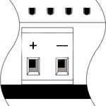 |
+24V GND |
+24 V — modul tápellátása külső 24 V-os tápegységről GND — közös |
 |
RJ45 | Csatlakozó LAN csatlakozáshoz |
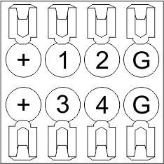
| In1-12, In13-24 GND | Vezérlő eszközök csatlakozása (gombok, mágneses reed kapcsolók, mozgás- vagy szivárgásérzékelők): +12V — érzékelő kimenet +12 V In1 … In24 — logikai bemenetek (0-12 V) GND — közös | |
 |
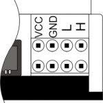
OneWire | Digitális érzékelők csatlakozása (hőmérséklet) VCC — érzékelők tápegység kimenete +5V OW1-OW4 — OneWire adatbuszok GND — közös |
 |
VCC GND L H |
Külső modulok csatlakozása CAN-buszhoz VСС — 24V kimenet külső eszközök tápellátásához GND — közös L — CAN-L adatbusz H — CAN-H adatbusz |
| Indicator | Status | Description |
|---|---|---|
| Power | Power | |
| Power not available | ||
| Activity | Data communication | |
| Data communication not available | ||
| Error | No errors | |
| Communication error | ||
| Module overheat | ||
| Dimmer outputs module overload | ||
| Absence of power on dimmers, if in configuration |
Rendszer telepítés és összeszerelés
A rendszer csatlakoztatása előtt a következőket kell tennie:
- Helyezze el az érzékelőt és a működtetőket (ha nincs előre telepítve), állítsa be az érzékelőket és a működtetőket;
- Helyezze el a modult és a tápegységet.
'Megjegyzés: A modult a tápfeszültségforrás közelében kell elhelyezni.
- A megszakító szerelvény teljesítményének meg kell felelnie a terhelhetőségnek;
- A modulhoz a fázisvezetőkön kívül semmi más nem köthető, a nulla vezetéket külön kell bekötni.
A METAFORSA MF-14 tipikus diagramja. A modulcsatlakozás a ábrán látható. 3.

A hajtóművek csatlakoztatása
A lámpák/elektromos kontaktor/fűtő-termikus működtető csatlakoztatása
 Fig. 4 |
Az állítóműveket, mint például a fény, az elektromos kontaktor, a fűtőtermikus szelepmozgatót az 1-10 kimenetek bármelyikére kell kapcsolni, a nulla vezetéket és a földelő vezetéket közvetlenül a kapcsolótáblára kell csatlakoztatni. A bekötési példa a ábrán látható. 4'. |
Nagy terhelésű készülék csatlakoztatása
 |
Ajánlott kontaktorok:
|
Egypólusú víz-/gázellátó szelep csatlakoztatása
| Caution: Before applying power to the load, make sure that the output configuration of METAFORSA module is correct. The incorrect configuration or incorrect connection can cause the module failure and/or failure of the equipment connected to it, and even a fire. | |
 Fig. 5 |
The single pole water/gas supply valve is connected to any of the outputs of 1 – 10, the (neutral wire and the ground wire are connected directly to the switchboard. The example of connection is shown in Fig.5. |
Connection of double-pole water/gas supply valve
| Caution: Before applying power to the valve, it is necessary to ensure the output configuration of METAFORSA module is correct. The incorrect configuration can cause the voltage application simultaneously to both channels of the valve, which may result in the module failure and/or failure of the equipment connected to it, and even a fire. | |
 Fig. 6 |
Two adjacent contact points (for example, 3, 4) are used to connect the double-pole water/gas supply valve; in these conditions the neutral wire and the ground wire are connected directly to the switchboard. The example of connection is shown in Fig.6. |
Connection of single-pole gate actuator
| Caution: Before applying power to the module, you should properly configure access to the application. The contacts incorrectly configured can result in the module failure and/or failure of the equipment connected to it, and even a fire.
| |
 Fig. 7 |
Any contact point (for example, 3) is used to connect the single-pole gate drive controllers. The example of connection is shown in Fig.7. |
Connection of double-pole gate actuator
| Caution: Before applying power to the module, you must properly configure the outputs in the application. The contacts configured incorrectly can lead to simultaneous power supply to both channels, resulting in the module failure and/or failure of the equipment connected to it, and even a fire.
| |
 Fig. 8 |
Two adjacent contact points (for example, 3, 4) should be used to connect the double-pole gate drive controller. The example of connection is shown in Fig.8. |
Connection of curtain/jalousie/shutter actuator with 220V force control
| Caution: Before applying power to the module, you must properly configure the outputs in the application. The contacts configured incorrectly can lead to simultaneous power supply to both channels, resulting in the module failure and/or failure of the equipment connected to it, and even a fire.
| |
 Fig. 9 |
Two adjacent contact points (for example, 3, 4) should be used to connect the curtain/jalousie/rolladens actuator, in these conditions the neutral wire and the ground wire are connected directly to the switchboard. The example of connection is shown in Fig.9. |
Connection of curtain/jalousie/shutter actuator with low-voltage control
| Caution: Before applying power to the module, you must properly configure the outputs in the application. The contacts configured incorrectly can lead to simultaneous power supply to both channels, resulting in the module failure and/or failure of the equipment connected to it, and even a fire.
| |
 Fig. 10 |
Two adjacent contact points (for example, 3, 4) should be used to connect the curtain/jalousie/rolladens actuator with low-voltage control. The example of connection is shown in Fig.10. |
Connection of sensing elements/switches/buttons
Connection of motion sensors
The motion sensors should be connected to any free input in1-in24; in these conditions their power is connected to the contact points of +12V and GND of the relevant group. The example of connection is shown in Fig.11.

Fig. 11
Connection of FW-WL.A leakage sensors
FW-WL.A leakage sensors are connected to any free input in1 – in24, in these conditions the power should be connected to +12V and GND points of the relevant group. The example of connection is shown in fig. 12.
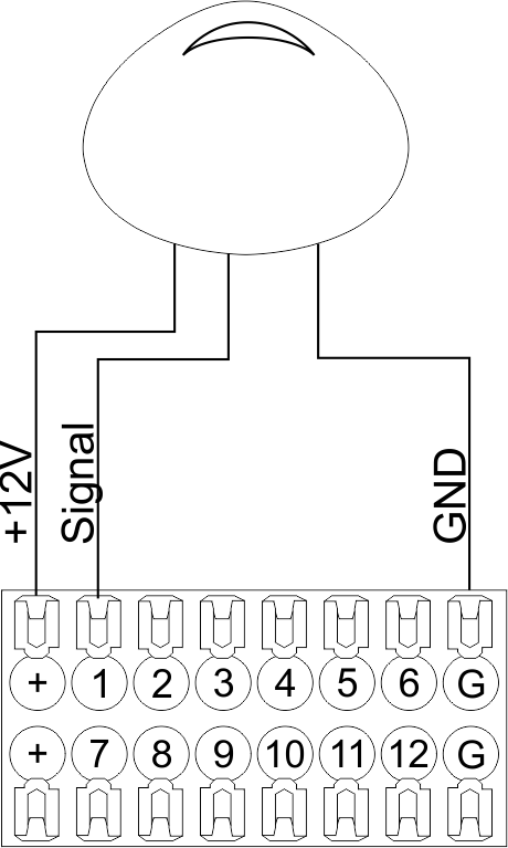 Fig12 |
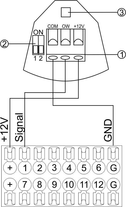 Fig13 |
Configuration and connection of the FW-WL.A sensor 1. Terminals:
- +12V — sensor power is connected to the contact point of METAFORSA “+12V”;
- OW — sensor pickup signal;
- GND — common, connected to GND contact of METAFORSA.
2. Sensor preset switch (optionally):
- 1 — sensor sensitivity (ON – high, OFF – low);
- 2 — indicator colour setting (ON – blue, OFF – green).
3. LED status indicator.
Connection of buttons/switches/magnetic reed switches
Buttons and reed switches are connected to any free input in1-in24, while their second contact point is connected to GND point of the relevant METAFORSA module group, + 12V power outputs – not in use. The example of connection is shown in Fig. 14-15.
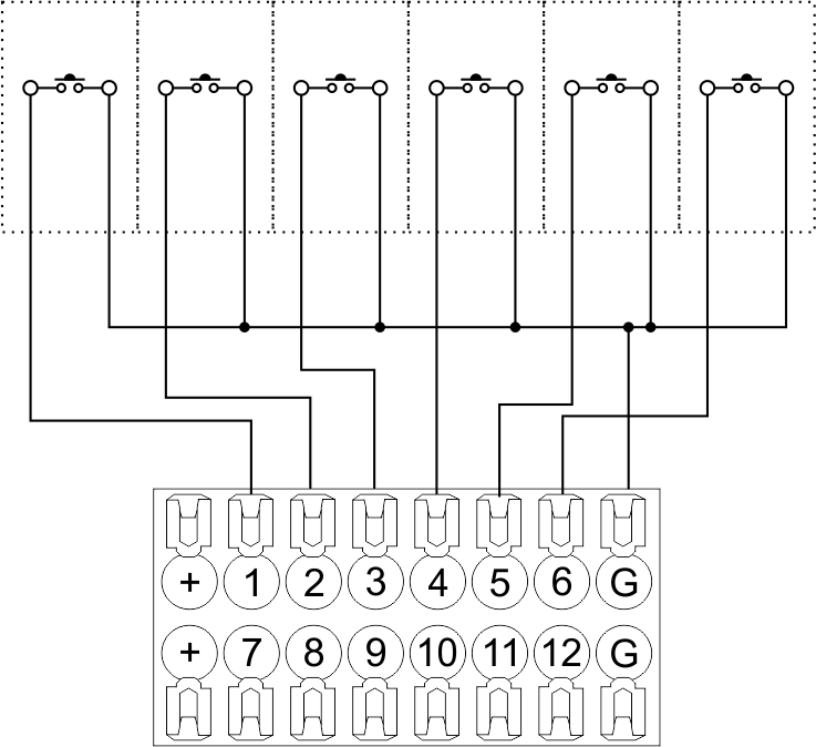 Fig14 connection of buttons/switching units |
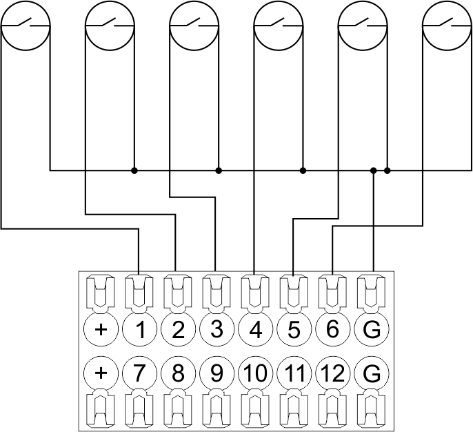 Fig15 connection of the magnetic reed switches (window/door position sensors) |
Connection of digital sensors
The OW adapter (Fig. 16a) is supplied along with METAFORSA module with the possibility to connect up to 8 digital sensors to it. In these conditions, several devices can be connected to one channel (Fig. 16b). The connected sensors are detected automatically and do not require any original setting.
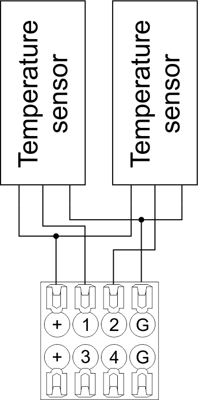 Fig16 a |
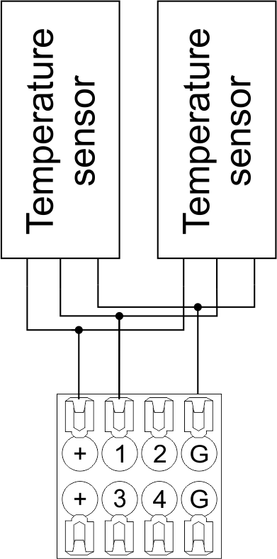 Fig16 b |
Configuration and connection of the OW adapter
Connection of auxiliary equipment.
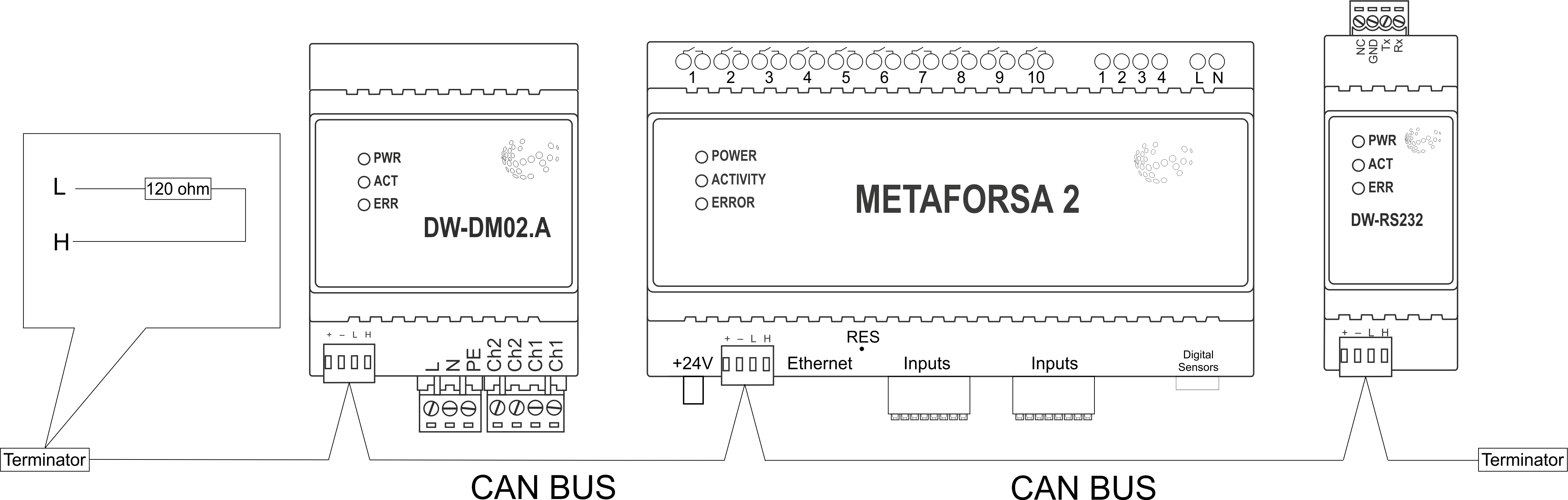
Expansion modules include Larnitech equipment connected through the CAN-bus. Such equipment includes: dimmers, RGB-backlit control modules, multimode sensors, etc. The equipment connected to the expansion port is defined automatically and does not require any preset tuning. Connector contact pin assignment is defined in Table 4. The example of connection is shown in Fig. 17.
|
| Caution! The 120 ohm terminating resistors should be installed at the end connectors between L and H contact points of CAN-bus. Ensure the connection is correct. The incorrect connection may cause sensor and/or module malfunction. |
Module installation and connection procedure
- Install the module in the switchboard on the DIN-rail and fix it with the special latch on the module base.
- Fasten the supply unit on the left side of the module.
- Connect the connector (4) having the noise filter pre-installed which is supplied complete with the module.
- Connect the connectors (5), (6).
- Connect the connectors (1), (2).
- Connect the connector (3).
- Apply power to the supply unit of METAFORSA module.
- Wait until the module is loaded, then configure it in accordance with the System Setup Instructions.
- Apply power to the connectors (1), (2).
- Check all equipment for proper operation.
METAFORSA module shut-off and deinstallation procedure
- De-energize the module by disconnecting the circuit breaker assembly of the load power supply and METAFORSA module supply unit. Verify the voltage is absent on the terminals (1), (2) of the connector wires and on the input terminals of the supply unit.
- Disconnect the load power supply connectors (1), (2).
- Disconnect the connector (3).
- Disconnect the connectors (4)-(6).
- Remove the module from the DIN-rail, releasing the latch at the bottom of the module base.
Hardware setup
To configure and control METAFORSA SMART HOUSE, you must install Larnitech software on your smartphone or tablet, which is available in App Store and Play Market. After installation, follow the System Setup Instructions.
Fault diagnostics and handling
The following are some possible faults and ways of fault handling. If you have any difficulty, or face the fault undeclared here, please contact the Technical Support: [1] or [support@larnitech.com]. There are also some tips in the FAQ section at our website [2].
The actuators do not operate:
- ensure the outputs are properly configured in the application (see System Setup Instructions);
- check the connection is correct in accordance with table 2 and paragraph 3.6;
- ensure the power is supplied to the input power contact , i.e. all circuit breaker assembly are ON.
- verify the operability of the connected equipment.
The module is off, indication absent:
- check the connection to 24V supply unit as shown in table 2 (contacts pin assignment);
- check the connection of the supply unit to 220V power mains, the indicator should be ON.
Network connection fault:
- ensure the Ethernet cable is properly wired and connected to the connector;
- ensure the LED status indicators are ON on the Ethernet connector;
- check the LAN configuration is correct, Ethernet cable loops are absent;
- METAFORSA module and the device you are connecting from are in the same network.
hold integer 0-10000 1-10 by default hold is the same as runtime hold is the bridging time in miliseconds, is used for gate and jalousie, lock; Example: hold=3500
The sensors do not operate:
- ensure the inputs are properly configured in the application (System Setup Instructions);
- check the connection is correct in accordance with table 2 and paragraph 3.7;
- ensure the METAFORSA module is ON: circuit breaker assembly is closed, indication on the supply unit is ON, the module indication corresponds to the operating status – table 3;
- check the power supply availability on the sensors;
- check the integrity of lines laid to the sensors.
The auxiliary equipment does not operate:
- check the connection is correct in accordance with table 2 and paragraph 3.8-9;
- ensure the METAFORSA module is ON: circuit breaker assembly is closed, indication on the supply unit is ON, the module indication corresponds to the operating status – table 3;
- check the integrity of the CAN lines, voltage supply on the modules.
HW Settings
| Name | Type, range | SUBID | Default | Description |
|---|---|---|---|---|
| runtime | integer 0-100 | 1-10 | 15 | runtime is the open/close time in seconds, is used for jalousie, gate, valve(2 pole);
|
| runtimeopen | integer 0-60000 | Blinds subId | Runtimeopen is the open time in milliseconds, is used for blinds; Example: runtimeopen=15000 | |
| runtimeclose | integer 0-60000 | Blinds subId | Runtimeclose is the close time in milliseconds, is used for blinds; Example: runtimeclose=15000 | |
| hold | integer 0-10000 | 1-10 | 500 | hold is the bridging time in milliseconds, is used for gate and jalousie (by default hold is the same as runtime for jalousie and gate), lock; Example: hold=3500 |
| def | string 'ON' | 1-10 | 'OFF' | def is the element status is set after restart, is used for lamp, heating, valve(1 pole); Example: def='ON' |
| stop | Char ‘R’ | 1-7 | – | (for 2-pole gate and blinds) If it is declared then by Stop command during the motion, the same impulse appears as it was at the beginning of the motion. Pole, an which the stop-impules is formed, is defined by the parameter Stop value. If it is ‘r’ or ‘R’ then stop-impulse is produced on the opposite to the start-impulse pole. If any other value is delcared (e.g., ‘d’ ) then the stop-impulse is on the same pole. If a Runtime passed after the beginning of the motion then the stop-impulse is not formed. Example: stop=’r’ |
| out | char[10] | 98 | 'LLLLHHHHP-' | Each char is responsible for the type of a particular channel
Example: out='LLB-G-V-W-' |
| dm | char[4] | 98 | ‘LLLL’ | Each char is responsible for the type of a particular channel
Example: dm=’skl-‘ |
| def | integer 0-250 | 11-14 | 100 | The default brightness level in case of a power reset (1..250). Example: def=250 |
| min | integer 0-100 | 11-14 | 0 | Minimum dimming level, example: min=10 |
| max | integer 0-100 | 11-14 | 100 | Maximum dimming level, example max=95 |
| start | integer 0-100 | 11-14 | 0 | The Start function is used for lamps that lack the minimal voltage to get turned on. If the set value is lower than the start value, the lamp is turned on at the start value and them the light is dimmed down to the set level. Example: start=60 |
| force | integer 0-100 | 11-14 | 10 | Time duration of the starting value (measured in milliseconds). Example: force=20 |
| runtime | integer 0-60000 | 11-14 | 1000 | Runtime is the speed of changing the brightness from ‘min’ to ‘max’ (measured in milliseconds). Example: runtime=1000 |
| offset | integer (+/- 0…39) | 39-46 | '0' | sensor values offset; For example, offset is -3.8 :
Example: hw="offset='-3.8'" |
| in | char[24] | 98 | 'BBBBBBBBBBBBMMMLLLKKKKKK' | Each char is responsible for the type of a particular channel
Example: in='MMMMMMMMMMMMLLLLLLLLLLLL' 12 motion sensors and 12 leak-sensors; in='BBBBBBBBSSSSSSBBBBSSSSSS' 12 buttons; 12 switches. |
 1<item addr="339:1" auto-period="600" cfgid="40" hw="def='ON'" name="Lamp" type="lamp" uniq_id="3779">
 2<item addr="339:2" cfgid="40" hw="def='ON'" name="Radiator" type="valve-heating" uniq_id="3780">
 3    <automation name="Eco" temperature-level="16" uniq_id="3781"/>
 4    <automation name="Comfort" temperature-level="22" uniq_id="3782"/>
 5    <automation name="Hot" temperature-level="25" uniq_id="3783"/>
 6</item>
 7<item addr="339:3" cfgid="40" hw="runtime=9" name="Jalousie" sub-type="120" type="jalousie" uniq_id="32"/>
 8<item addr="339:5" cfgid="40" hw="runtime=13" name="Gate" sub-type="120" type="gate" uniq_id="3784"/>
 9<item addr="339:7" cfgid="40" hw="hold=4600" name="Gate" sub-type="120" type="gate" uniq_id="3785"/>
10<item addr="339:8" cfgid="40" hw="runtime=10" name="Valve" type="valve" uniq_id="3786"/>
11<item addr="339:11" cfgid="40" name="Motion" type="motion-sensor" uniq_id="17"/>
12<item addr="339:12" cfgid="40" name="Motion" type="motion-sensor" uniq_id="18"/>
13<item addr="339:13" cfgid="40" name="Motion" type="motion-sensor" uniq_id="19"/>
14<item addr="339:16" cfgid="40" name="Leak" type="leak-sensor" uniq_id="21"/>
15<item addr="339:17" cfgid="40" name="Leak" type="leak-sensor" uniq_id="41"/>
16<item addr="339:19" cfgid="40" name="Switch" type="switch" uniq_id="22"/>
17<item addr="339:20" cfgid="40" name="Switch" type="switch" uniq_id="23"/>
18<item addr="339:21" cfgid="40" name="Switch" type="switch" uniq_id="24"/>
19<item addr="339:22" cfgid="40" name="Switch" type="switch" uniq_id="25"/>
20<item addr="339:23" cfgid="40" name="Door" type="door-sensor" uniq_id="26"/>
21<item addr="339:24" cfgid="40" name="Door" type="door-sensor" uniq_id="27"/>
22<item addr="339:25" cfgid="40" name="Door" type="door-sensor" uniq_id="28"/>
23<item addr="339:26" cfgid="40" name="Door" type="door-sensor" uniq_id="29"/>
24<item addr="339:30" cfgid="40" name="Temperature" type="temperature-sensor" uniq_id="3772"/>
25<item addr="339:31" cfgid="40" name="Temperature" type="temperature-sensor" uniq_id="3773"/>
26<item addr="339:32" cfgid="40" name="Temperature" type="temperature-sensor" uniq_id="3774"/>
27<item addr="339:33" cfgid="40" hw="offset='-10.8'" name="Temperature" type="temperature-sensor" uniq_id="3775"/>
28<item addr="339:34" cfgid="40" hw="offset='25.1'" name="Temperature" type="temperature-sensor" uniq_id="3776"/>
29<item addr="339:35" cfgid="40" name="Temperature" type="temperature-sensor" uniq_id="3777"/>
30<item addr="339:36" cfgid="40" name="Temperature" type="temperature-sensor" uniq_id="3778"/>
31<item addr="339:98" cfgid="40" hw="out='LHB-G-XV--' in='MMM--LL-BBBBKKKK'" name="Temperature" system="yes" type="temperature-sensor" uniq_id="30"/>