Metaforsa2 MF-14
| MF-14 | |||||||||||||
|---|---|---|---|---|---|---|---|---|---|---|---|---|---|
 | |||||||||||||
| |||||||||||||
| |||||||||||||
| |||||||||||||
Įvadas
METAFORSA SMART HOUSE montavimo vadove aprašoma jo įrengimo, surinkimo, veikimo ir nustatymo procedūra. Dirbdami su sistema turite griežtai laikytis visų šiame vadove nustatytų reikalavimų. Nesilaikant reikalavimų, gali būti sugadintas įrenginys, jo gedimas, elektros smūgis, gaisras ir kiti krituliai. Gamintojas pasilieka teisę keisti šį vadovą be išankstinio įspėjimo. Šis vadovas yra neatskiriama sistemos dalis ir lieka galutiniam vartotojui.
Savybės
- 10 universalių išėjimų palaikymas:
- Šviesos
- NC/NO šildymo vožtuvai
- Žaliuzės
- 1 arba 2 polių vartai
- 1 arba 2 polių vožtuvai
- NC/NO užraktai
- Ventiliatoriaus ritės blokai
- 4 pritemdymo išėjimai
- 24 diskretiškos įvestys, kurios palaiko:
- Mygtukai
- Jungikliai
- nendriniai jungikliai
- nuotėkio jutikliai
- judesio detektoriai
- 4 skaitmeniniai įėjimai iki 8 temperatūros jutiklių
- Prailginimo prievadas
- Relės su AgSnO2 kontaktais, kurių vardinė srovė yra 80A 20ms
- Debesų prijungimas ir visų namų sistemų valdymas
- Valdymas balsu („Siri“, „Alexa“, „Google Home“)
- Įskiepių variklis leidžia išplėsti sistemos galimybes (pvz., integruoti su Satel, Philips Hue, IKEA lemputėmis)
- Saugumas nuo neteisėto įsibrovimo užtikrinamas naudojant RSA/AES256 šifravimą
- Push pranešimus iš sistemos savo telefone (taip pat galima gauti per Telegram ir Viber Messengers)
- Istorija (skaitiklio duomenys saugomi 1 metus)
- Plug and play (galimybė greitai ir patogiai išplėsti sistemą)
- Reguliarūs sistemos atnaujinimai
- Didelė nuolat atnaujinama scenarijų duomenų bazė, atitinkanti visus jūsų poreikius
- Automatinės kasdienės atsarginės kopijos per debesį su galimybe atkurti pradinę konfigūraciją
- Atvira API (kuri leidžia integruoti Larnitech į kitas sistemas)
- Pažangiajai konfigūracijai prieinama interaktyvi ir patogi LT SETUP žiniatinklio sąsaja
- Prijunkite ir žaiskite
- Tai visiškai įdiegimui paruoštas Smart Home sistemos rinkinys
Saugos reikalavimai
Kad išvengtumėte gaisro, elektros smūgio, sistemos sugadinimo ir (arba) sužalojimo pavojaus, sistemos montavimas ir surinkimas turi būti atliekami pagal toliau pateiktas instrukcijas:
- visi prijungimo darbai turi būti atliekami be maitinimo;
- naudoti tinkamus įrankius ir asmenines apsaugos priemones nuo elektros smūgio;
- nenaudokite pažeistų kabelių, laidų ir jungčių;
- venkite kabelių ir laidų lankstymo;
- nesuspauskite ir nesulenkite kabelių ir laidų naudodami per didelę jėgą. Priešingu atveju vidiniai kabelio ir laidų laidininkai gali būti nulupti arba nutrūkę;
- jungti nenaudokite maitinimo lizdo su prastais kontaktais;
- neviršyti šiame vadove nurodytos apkrovos parametrų ribos;
- maitinimo laidų laidų sekcijai taikomos srovės tankio ribos, izoliacijos tipo ir laido medžiagos specifikacijos. Dėl lengvos dalies kabelis gali perkaisti ir sukelti gaisrą.
Kai dirbate su sistema po įtampos tiekimo NIEKADA:
- padaryti jungčių pajungimą/atjungimą;
- atviri moduliai ir jutikliai.
Sistemos konfigūracija ir paskirtis
Sistemos paskirtis
METAFORSA SMART HOUSE – tai paruoštas sprendimas gyvenamųjų ir komercinių patalpų, viešbučių kompleksų automatizavimui, apimantis labiausiai pageidaujamas Smart House savybes.
Įrenginys turi 10 valdymo kanalų, 4 pritemdymo kanalus, 24 įeinančius jutiklių kanalus ir skaitmeninių jutiklių prijungimo prievadą.
| Universalūs išėjimai gali būti naudojami valdyti: | Universalūs įėjimai leidžia prijungti: |
|---|---|
| Apšvietimas | Mygtukai / perjungimo blokai |
| Kištukinės jungtys | Magnetiniai nendriniai jungikliai |
| Grindinis šildymas | Judesio jutikliai |
| Užuolaidų/vartų pavaros | Nuotėkio jutikliai |
| Vandens tiekimo/šildymo vožtuvai |
Skaitmeninių jutiklių prijungimo prievadas
Skaitmeninių jutiklių prijungimo prievadas leidžia prijungti įvairius skaitmeninius jutiklius, tokius kaip temperatūros, aplinkos šviesos, drėgmės ir kt.
Išplėtimo prievadas
Išplėtimo prievadas leidžia atnaujinti sistemą prijungiant pagalbinę įrangą, tokią kaip LED apšvietimo valdymo modulis, reguliavimas, matavimo prietaisai ir kiti elementai.
Į paketą, kuris yra visiškai paruoštas įdiegti, yra pagrindinė aparatinė ir programinė įranga.
Paketo turinys
Standartiškai komplekte yra:
| Pagrindinis kompiuteris METAFORSA MF-14.А | 1 vnt |
| Maitinimo blokas MEANWELL DR-15-12 | 1 vnt |
| Judesio jutiklis CW-MSD | 3 vnt |
| Nuotėkio jutiklis FW-WL.A | 2 vnt |
| Temperatūrai jautrus elementas FW-TS.A | 4 vnt |
| Magnetinis nendrinis jungiklis (lango/durų padėties jutiklis) | 4 vnt |
| Eterneto kabelio triukšmo filtras | 1 vnt |
| Maitinimo laidas | 1 vnt |
Pagrindinės techninės sistemos specifikacijos
Pagrindinės modulio METAFORSA MF-14.A specifikacijos ir charakteristikos pateiktos 1 lentelėje
| Specifikacija | Reikšmė |
|---|---|
| Išvesties prievadai | |
| Perjungtų kanalų skaičius | 10 |
| Perjungtų grupių skaičius | 10 |
| Pritemdančių kanalų skaičius | 4 |
| Komutavimo įtampa | 0-250 V AC/DC |
| Didžiausia apkrova (vienas kanalas) | 16A |
| Didžiausia apkrova (įrenginys) | 160A |
| Maksimali apkrova vienam pritemdymo kanalui | 0,5 A (110 W, esant 220 V) |
| Dimmer tipas | MOSFET |
| Dimmer apkrovos tipas | R, C |
| Pritemdymo tipas | galinis kraštas |
| Maitinimo kabelio jungties tipas | jungtis |
| Leidžiama maitinimo laido dalis, kurią galima jungti į lizdą: vieno laido kabelis daugelio laidų laidas daugelio laidų kabelis su galiukais |
0,5 … 4mm2 0,5 … 4mm2 0,5 … 2,5 mm2 |
| Įvesties prievadai | |
| Diskrečiųjų įėjimų skaičius | 24 |
| Skaitmeninių įėjimų skaičius | 4 |
| Maksimali srovė nuolatinės srovės įtampos jungtyse | 50mA |
| Kita | |
| Darbinė aplinkos temperatūra | 0 … +45°С |
| Laikymo/gabenimo temperatūra | -20 … +60°С |
| Leidžiama drėgmė | 0…95 % (nekondensuojantis) |
| Maitinimas | 12 … 27,5 V DC 24 V, 0,75 A rekomenduojama |
| Maksimali paklausa | 0,5А |
| Galimos sąsajos | Ethernet, CAN, OneWire |
| Autobuso tipas | CAN (4 laidų) |
| CAN (4 laidų) | 800 m* (vyta pora 5 katės) |
| CAN laido tipas | FTP Cat 5E |
| CAN ryšio tipas | jungtis |
| Didžiausias skaitmeninės linijos ilgis | 30 m |
| Skaitmeninės linijos laido tipas | UTP/FTP Cat 5E |
| LAN maksimalus ilgis | 100 m |
| LAN laido tipas | UTP/FTP Cat 5E |
| LAN ryšio tipas | Jungtis RJ-45 |
| Matmenų specifikacijos | 9U, 156x110x58 mm |
| Kauto medžiaga | ABS plastikas |
| Apvalkalas | IP40 |
| Įrangos įrengimo tipas | DIN bėgis (EN 60715) |
| Svoris | 400 g |
* – ilgoms linijoms reikia įrengti papildomus maitinimo blokus; maksimalus linijos ilgis gali būti sumažintas dėl įvairių trukdžių veiksnių
Bendra sistemos struktūra
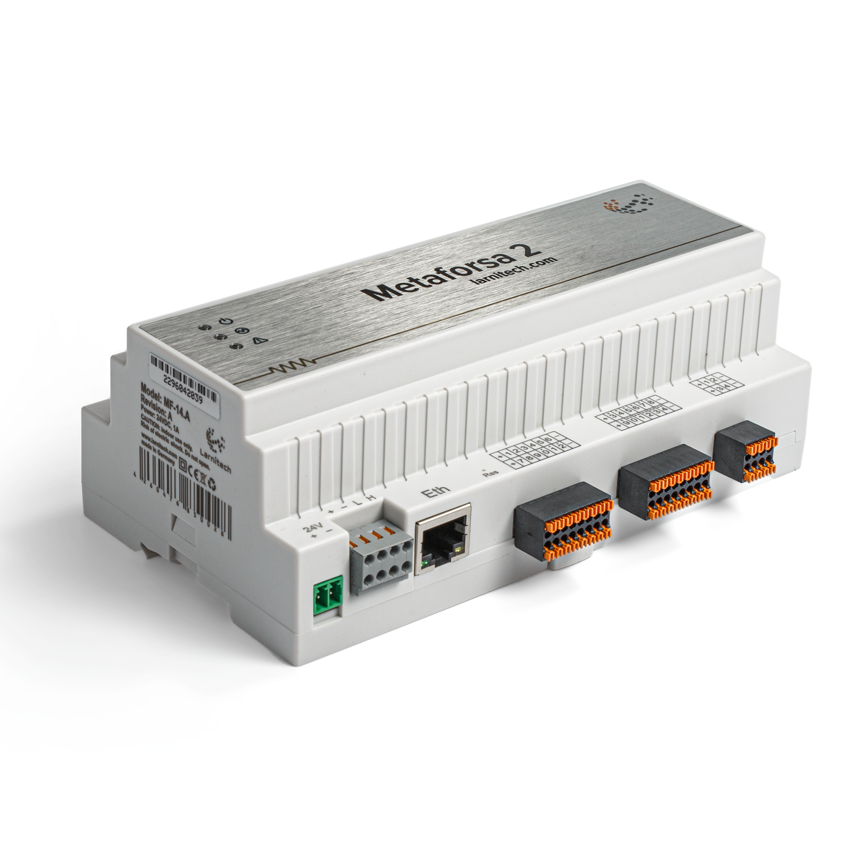
Bendras modulio vaizdas parodytas pav. 1'

| 1 | — jungtis apkrovai pritaikyti |
| 2 | — jungtis, skirta pritemdymo lempoms naudoti |
| 3 | - maitinimo jungtis |
| 4 | — Ethernet tinklo jungtis |
| 5-6 | — skaitmeninių jutiklių ir mygtukų / perjungimo blokų jungtys |
| 7 | — OneWire sąsajos jungtis (skaitmeniniams jutikliams) |
| 8 | — išplėtimo modulio jungtis. |
MetaFORSA įrenginio išorinių jungčių apžvalga:'
Korpuso viršuje ('1 pav.) yra:
- jungtis (1) — Įrenginių prijungimas;
- jungtis (2) — Pritemdymo lempų jungtis;
Korpuso apačioje ('1 pav.) yra:
- jungtis (3) — modulio maitinimo jungtis;
- jungtis (4) — Ethernet tinklo jungtis;
- jungtys (5-6) — keturios šešių taškų jungtys skaitmeninių jutiklių prijungimui – judesio, nuotėkio, nendrinių jungiklių davikliai ir *mygtukų/perjungimo bloko jutikliai;
- jungtis (7) — OneWire skaitmeninių jutiklių magistralės jungtis;
- jungtis (8) — išplėtimo modulio jungtis.
Kiekvienos jungties fizinė konfigūracija ir kontaktinio taško priskyrimas rodomi '2 lentelėje.
| Jungtis | Kontaktai | Užduotis |
|---|---|---|
 |
1-10 | Apkrovos taikymas (šviesos lempos, šiluminės pavaros ir kt.) |
| D1-4, L, N | Apkrovos taikymas (pritemdymo lempos) | |
| Device status indicators | Modulio būsenos indikatoriai aprašyti ''3 lentelėje | |
 |
+24V GND |
+24 V — modulio maitinimas iš išorinio 24 V maitinimo šaltinio GND — bendras |
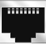 |
RJ45 | Jungtis LAN ryšiui |
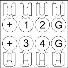
| In1-12, In13-24 GND | Valdymo įrenginių prijungimas (mygtukai, magnetiniai nendriniai jungikliai, judesio ar nuotėkio jutikliai): +12V – jutiklio išėjimo galia +12 V In1 … In24 – loginiai įėjimai (0-12 V) GND – bendras | |
 |
OneWire | Skaitmeninių jutiklių prijungimas (temperatūra) VCC — jutiklių maitinimo išėjimas +5V OW1-OW4 — OneWire duomenų magistralės GND — bendras |
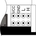 |
VCC GND L H |
Išorinių modulių jungtis CAN magistralei VСС — 24 V išėjimas išorinių įrenginių maitinimo šaltiniui GND — bendras L — CAN-L duomenų magistralė H — CAN-H duomenų magistralė |
| Indicator | Status | Description |
|---|---|---|
| Power | Power | |
| Power not available | ||
| Activity | Data communication | |
| Data communication not available | ||
| Error | No errors | |
| Communication error | ||
| Module overheat | ||
| Dimmer outputs module overload | ||
| Absence of power on dimmers, if in configuration |
Sistemos montavimas ir surinkimas
Prieš prijungdami sistemą, turite:
- patalpinkite jutiklį ir pavaras (jei nėra iš anksto sumontuotos), nustatykite jutiklius ir pavaras;
- Padėkite modulį ir maitinimo šaltinį.
'Pastaba: Modulis turi būti sumontuotas šalia maitinimo įtampos šaltinio.
- Automatinio jungiklio galia turi atitikti keliamąją galią;
- Prie modulio negalima prijungti nieko kito, išskyrus fazinius laidus, nulinis laidas jungiamas atskirai.
Tipinė METAFORSA MF-14.A modulio prijungimo schema parodyta pav. 3.

Pavarų prijungimas
Connection of the lights/electric contactor/heating thermal actuator
 Fig. 4 |
Such actuators as light, electric contactor, heating thermal actuator should be switched on any of the outputs 1 – 10, the neutral wire and the ground wire should be connected directly to the switchboard. The example of connection is shown in Fig.4. |
Connection of high load device
 |
Recomended contactors:
|
Connection of single-pole water/gas supply valve
| Caution: Before applying power to the load, make sure that the output configuration of METAFORSA module is correct. The incorrect configuration or incorrect connection can cause the module failure and/or failure of the equipment connected to it, and even a fire. | |
 Fig. 5 |
The single pole water/gas supply valve is connected to any of the outputs of 1 – 10, the (neutral wire and the ground wire are connected directly to the switchboard. The example of connection is shown in Fig.5. |
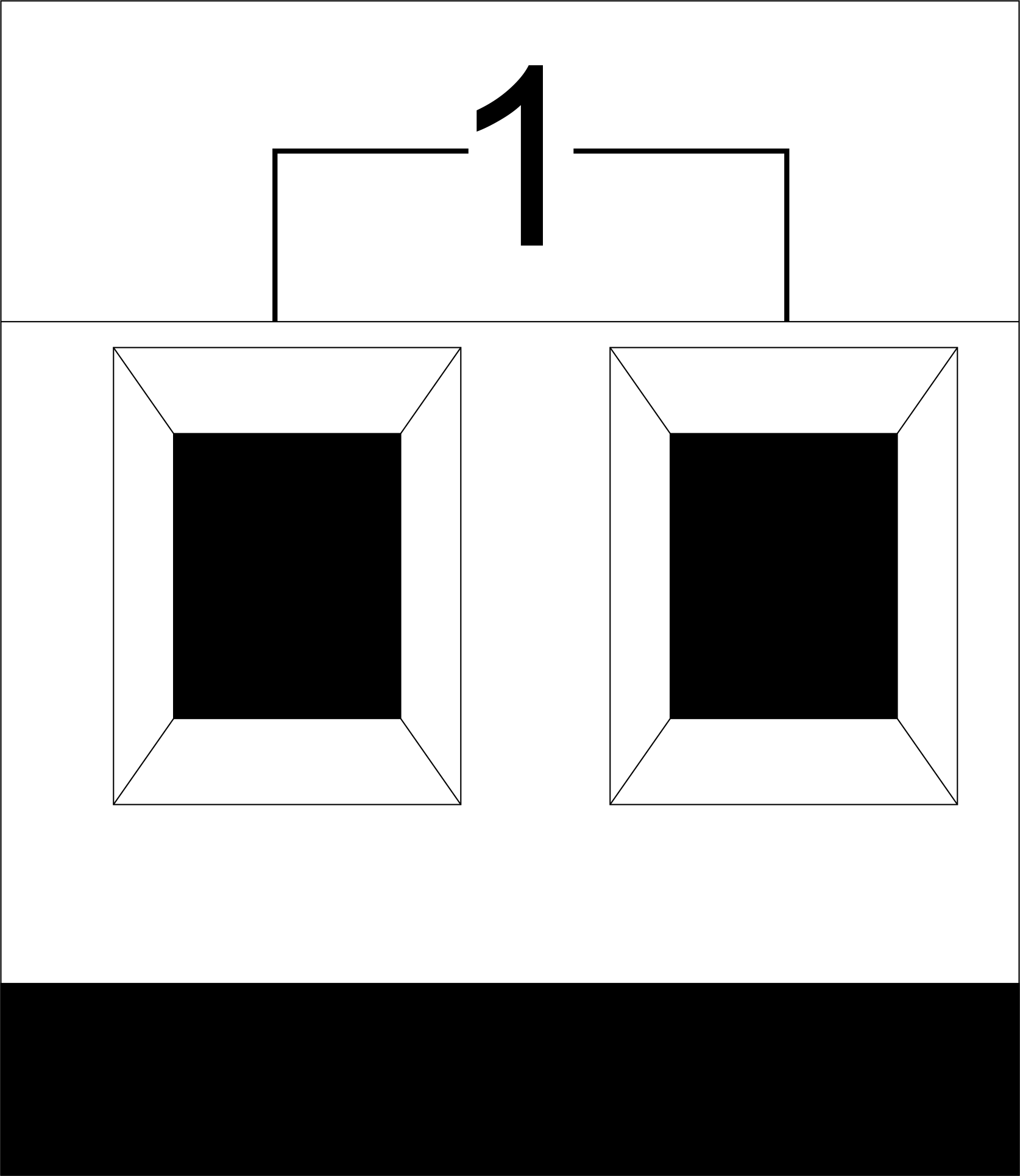
Connection of double-pole water/gas supply valve
| Caution: Before applying power to the valve, it is necessary to ensure the output configuration of METAFORSA module is correct. The incorrect configuration can cause the voltage application simultaneously to both channels of the valve, which may result in the module failure and/or failure of the equipment connected to it, and even a fire. | |
 Fig. 6 |
Two adjacent contact points (for example, 3, 4) are used to connect the double-pole water/gas supply valve; in these conditions the neutral wire and the ground wire are connected directly to the switchboard. The example of connection is shown in Fig.6. |
Connection of single-pole gate actuator
| Caution: Before applying power to the module, you should properly configure access to the application. The contacts incorrectly configured can result in the module failure and/or failure of the equipment connected to it, and even a fire.
| |
 Fig. 7 |
Any contact point (for example, 3) is used to connect the single-pole gate drive controllers. The example of connection is shown in Fig.7. |
Connection of double-pole gate actuator
| Caution: Before applying power to the module, you must properly configure the outputs in the application. The contacts configured incorrectly can lead to simultaneous power supply to both channels, resulting in the module failure and/or failure of the equipment connected to it, and even a fire.
| |
 Fig. 8 |
Two adjacent contact points (for example, 3, 4) should be used to connect the double-pole gate drive controller. The example of connection is shown in Fig.8. |
Connection of curtain/jalousie/shutter actuator with 220V force control
| Caution: Before applying power to the module, you must properly configure the outputs in the application. The contacts configured incorrectly can lead to simultaneous power supply to both channels, resulting in the module failure and/or failure of the equipment connected to it, and even a fire.
| |
 Fig. 9 |
Two adjacent contact points (for example, 3, 4) should be used to connect the curtain/jalousie/rolladens actuator, in these conditions the neutral wire and the ground wire are connected directly to the switchboard. The example of connection is shown in Fig.9. |
Connection of curtain/jalousie/shutter actuator with low-voltage control
| Caution: Before applying power to the module, you must properly configure the outputs in the application. The contacts configured incorrectly can lead to simultaneous power supply to both channels, resulting in the module failure and/or failure of the equipment connected to it, and even a fire.
| |
 Fig. 10 |
Two adjacent contact points (for example, 3, 4) should be used to connect the curtain/jalousie/rolladens actuator with low-voltage control. The example of connection is shown in Fig.10. |
Connection of sensing elements/switches/buttons
Connection of motion sensors
The motion sensors should be connected to any free input in1-in24; in these conditions their power is connected to the contact points of +12V and GND of the relevant group. The example of connection is shown in Fig.11.

Fig. 11
Connection of FW-WL.A leakage sensors
FW-WL.A leakage sensors are connected to any free input in1 – in24, in these conditions the power should be connected to +12V and GND points of the relevant group. The example of connection is shown in fig. 12.
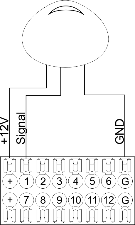 Fig12 |
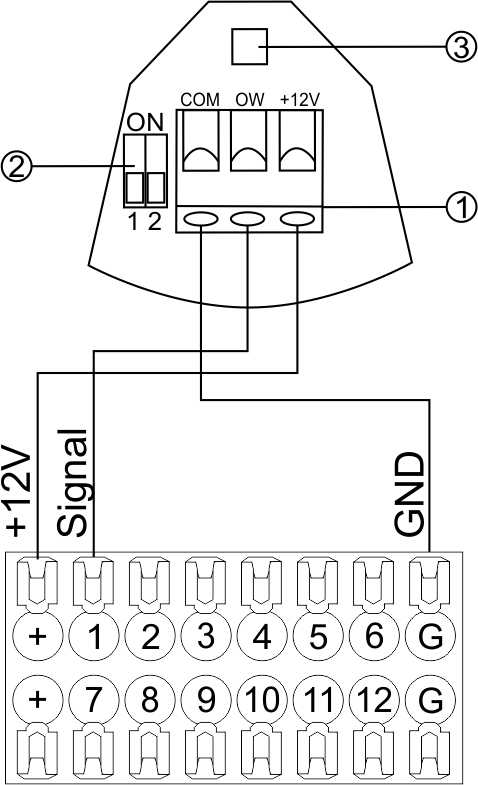 Fig13 |
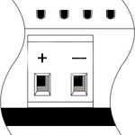
Configuration and connection of the FW-WL.A sensor 1. Terminals:
- +12V — sensor power is connected to the contact point of METAFORSA “+12V”;
- OW — sensor pickup signal;
- GND — common, connected to GND contact of METAFORSA.
2. Sensor preset switch (optionally):
- 1 — sensor sensitivity (ON – high, OFF – low);
- 2 — indicator colour setting (ON – blue, OFF – green).
3. LED status indicator.
Connection of buttons/switches/magnetic reed switches
Buttons and reed switches are connected to any free input in1-in24, while their second contact point is connected to GND point of the relevant METAFORSA module group, + 12V power outputs – not in use. The example of connection is shown in Fig. 14-15.
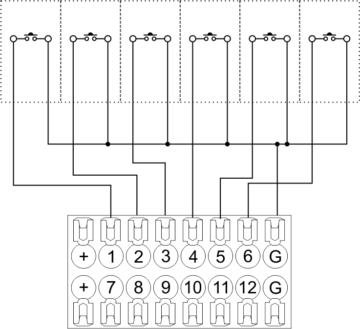 Fig14 connection of buttons/switching units |
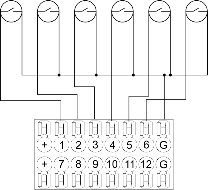 Fig15 connection of the magnetic reed switches (window/door position sensors) |
Connection of digital sensors
The OW adapter (Fig. 16a) is supplied along with METAFORSA module with the possibility to connect up to 8 digital sensors to it. In these conditions, several devices can be connected to one channel (Fig. 16b). The connected sensors are detected automatically and do not require any original setting.
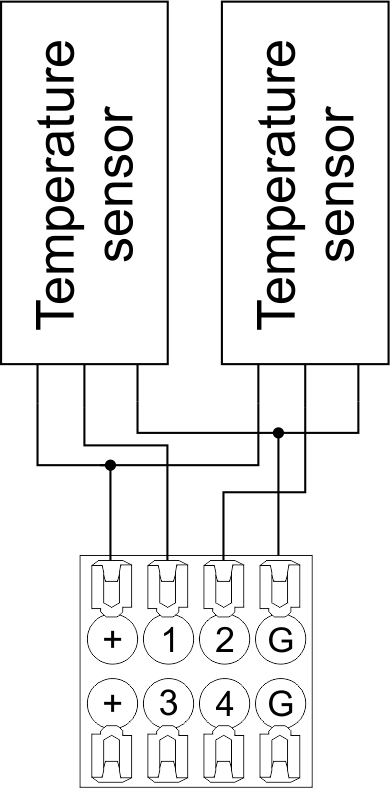 Fig16 a |
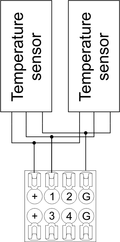 Fig16 b |
Configuration and connection of the OW adapter
Connection of auxiliary equipment.
Expansion modules include Larnitech equipment connected through the CAN-bus. Such equipment includes: dimmers, RGB-backlit control modules, multimode sensors, etc. The equipment connected to the expansion port is defined automatically and does not require any preset tuning. Connector contact pin assignment is defined in Table 4. The example of connection is shown in Fig. 17.
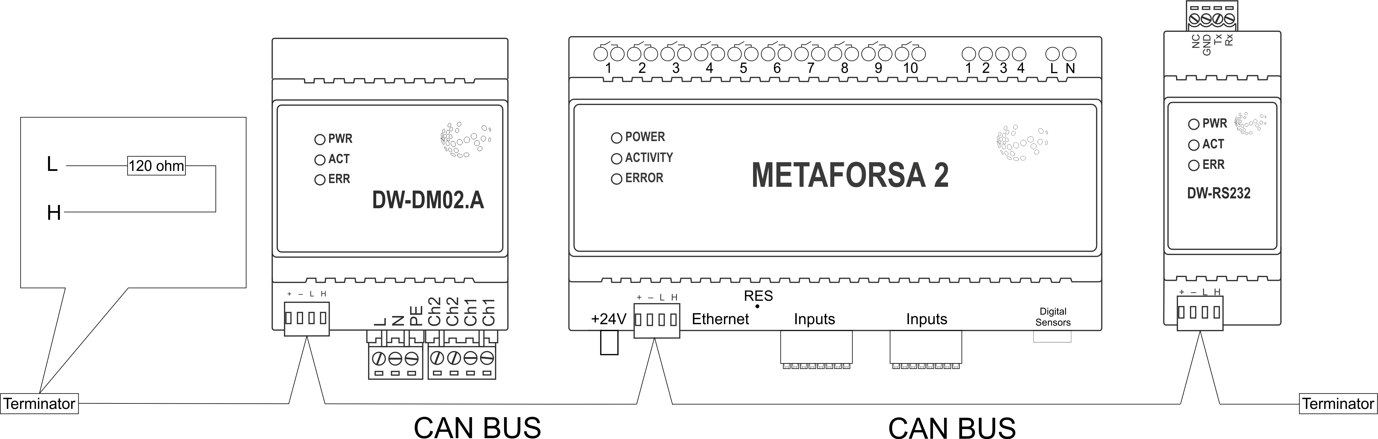
|
| Caution! The 120 ohm terminating resistors should be installed at the end connectors between L and H contact points of CAN-bus. Ensure the connection is correct. The incorrect connection may cause sensor and/or module malfunction. |
Module installation and connection procedure
- Install the module in the switchboard on the DIN-rail and fix it with the special latch on the module base.
- Fasten the supply unit on the left side of the module.
- Connect the connector (4) having the noise filter pre-installed which is supplied complete with the module.
- Connect the connectors (5), (6).
- Connect the connectors (1), (2).
- Connect the connector (3).
- Apply power to the supply unit of METAFORSA module.
- Wait until the module is loaded, then configure it in accordance with the System Setup Instructions.
- Apply power to the connectors (1), (2).
- Check all equipment for proper operation.
METAFORSA module shut-off and deinstallation procedure
- De-energize the module by disconnecting the circuit breaker assembly of the load power supply and METAFORSA module supply unit. Verify the voltage is absent on the terminals (1), (2) of the connector wires and on the input terminals of the supply unit.
- Disconnect the load power supply connectors (1), (2).
- Disconnect the connector (3).
- Disconnect the connectors (4)-(6).
- Remove the module from the DIN-rail, releasing the latch at the bottom of the module base.
Hardware setup
To configure and control METAFORSA SMART HOUSE, you must install Larnitech software on your smartphone or tablet, which is available in App Store and Play Market. After installation, follow the System Setup Instructions.
Fault diagnostics and handling
The following are some possible faults and ways of fault handling. If you have any difficulty, or face the fault undeclared here, please contact the Technical Support: [1] or [support@larnitech.com]. There are also some tips in the FAQ section at our website [2].
The actuators do not operate:
- ensure the outputs are properly configured in the application (see System Setup Instructions);
- check the connection is correct in accordance with table 2 and paragraph 3.6;
- ensure the power is supplied to the input power contact , i.e. all circuit breaker assembly are ON.
- verify the operability of the connected equipment.
The module is off, indication absent:
- check the connection to 24V supply unit as shown in table 2 (contacts pin assignment);
- check the connection of the supply unit to 220V power mains, the indicator should be ON.
Network connection fault:
- ensure the Ethernet cable is properly wired and connected to the connector;
- ensure the LED status indicators are ON on the Ethernet connector;
- check the LAN configuration is correct, Ethernet cable loops are absent;
- METAFORSA module and the device you are connecting from are in the same network.
hold integer 0-10000 1-10 by default hold is the same as runtime hold is the bridging time in miliseconds, is used for gate and jalousie, lock; Example: hold=3500
The sensors do not operate:
- ensure the inputs are properly configured in the application (System Setup Instructions);
- check the connection is correct in accordance with table 2 and paragraph 3.7;
- ensure the METAFORSA module is ON: circuit breaker assembly is closed, indication on the supply unit is ON, the module indication corresponds to the operating status – table 3;
- check the power supply availability on the sensors;
- check the integrity of lines laid to the sensors.
The auxiliary equipment does not operate:
- check the connection is correct in accordance with table 2 and paragraph 3.8-9;
- ensure the METAFORSA module is ON: circuit breaker assembly is closed, indication on the supply unit is ON, the module indication corresponds to the operating status – table 3;
- check the integrity of the CAN lines, voltage supply on the modules.
HW Settings
| Name | Type, range | SUBID | Default | Description |
|---|---|---|---|---|
| runtime | integer 0-100 | 1-10 | 15 | runtime is the open/close time in seconds, is used for jalousie, gate, valve(2 pole);
|
| runtimeopen | integer 0-60000 | Blinds subId | Runtimeopen is the open time in milliseconds, is used for blinds; Example: runtimeopen=15000 | |
| runtimeclose | integer 0-60000 | Blinds subId | Runtimeclose is the close time in milliseconds, is used for blinds; Example: runtimeclose=15000 | |
| hold | integer 0-10000 | 1-10 | 500 | hold is the bridging time in milliseconds, is used for gate and jalousie (by default hold is the same as runtime for jalousie and gate), lock; Example: hold=3500 |
| def | string 'ON' | 1-10 | 'OFF' | def is the element status is set after restart, is used for lamp, heating, valve(1 pole); Example: def='ON' |
| stop | Char ‘R’ | 1-7 | – | (for 2-pole gate and blinds) If it is declared then by Stop command during the motion, the same impulse appears as it was at the beginning of the motion. Pole, an which the stop-impules is formed, is defined by the parameter Stop value. If it is ‘r’ or ‘R’ then stop-impulse is produced on the opposite to the start-impulse pole. If any other value is delcared (e.g., ‘d’ ) then the stop-impulse is on the same pole. If a Runtime passed after the beginning of the motion then the stop-impulse is not formed. Example: stop=’r’ |
| out | char[10] | 98 | 'LLLLHHHHP-' | Each char is responsible for the type of a particular channel
Example: out='LLB-G-V-W-' |
| dm | char[4] | 98 | ‘LLLL’ | Each char is responsible for the type of a particular channel
Example: dm=’skl-‘ |
| def | integer 0-250 | 11-14 | 100 | The default brightness level in case of a power reset (1..250). Example: def=250 |
| min | integer 0-100 | 11-14 | 0 | Minimum dimming level, example: min=10 |
| max | integer 0-100 | 11-14 | 100 | Maximum dimming level, example max=95 |
| start | integer 0-100 | 11-14 | 0 | The Start function is used for lamps that lack the minimal voltage to get turned on. If the set value is lower than the start value, the lamp is turned on at the start value and them the light is dimmed down to the set level. Example: start=60 |
| force | integer 0-100 | 11-14 | 10 | Time duration of the starting value (measured in milliseconds). Example: force=20 |
| runtime | integer 0-60000 | 11-14 | 1000 | Runtime is the speed of changing the brightness from ‘min’ to ‘max’ (measured in milliseconds). Example: runtime=1000 |
| offset | integer (+/- 0…39) | 39-46 | '0' | sensor values offset; For example, offset is -3.8 :
Example: hw="offset='-3.8'" |
| in | char[24] | 98 | 'BBBBBBBBBBBBMMMLLLKKKKKK' | Each char is responsible for the type of a particular channel
Example: in='MMMMMMMMMMMMLLLLLLLLLLLL' 12 motion sensors and 12 leak-sensors; in='BBBBBBBBSSSSSSBBBBSSSSSS' 12 buttons; 12 switches. |
 1<item addr="339:1" auto-period="600" cfgid="40" hw="def='ON'" name="Lamp" type="lamp" uniq_id="3779">
 2<item addr="339:2" cfgid="40" hw="def='ON'" name="Radiator" type="valve-heating" uniq_id="3780">
 3    <automation name="Eco" temperature-level="16" uniq_id="3781"/>
 4    <automation name="Comfort" temperature-level="22" uniq_id="3782"/>
 5    <automation name="Hot" temperature-level="25" uniq_id="3783"/>
 6</item>
 7<item addr="339:3" cfgid="40" hw="runtime=9" name="Jalousie" sub-type="120" type="jalousie" uniq_id="32"/>
 8<item addr="339:5" cfgid="40" hw="runtime=13" name="Gate" sub-type="120" type="gate" uniq_id="3784"/>
 9<item addr="339:7" cfgid="40" hw="hold=4600" name="Gate" sub-type="120" type="gate" uniq_id="3785"/>
10<item addr="339:8" cfgid="40" hw="runtime=10" name="Valve" type="valve" uniq_id="3786"/>
11<item addr="339:11" cfgid="40" name="Motion" type="motion-sensor" uniq_id="17"/>
12<item addr="339:12" cfgid="40" name="Motion" type="motion-sensor" uniq_id="18"/>
13<item addr="339:13" cfgid="40" name="Motion" type="motion-sensor" uniq_id="19"/>
14<item addr="339:16" cfgid="40" name="Leak" type="leak-sensor" uniq_id="21"/>
15<item addr="339:17" cfgid="40" name="Leak" type="leak-sensor" uniq_id="41"/>
16<item addr="339:19" cfgid="40" name="Switch" type="switch" uniq_id="22"/>
17<item addr="339:20" cfgid="40" name="Switch" type="switch" uniq_id="23"/>
18<item addr="339:21" cfgid="40" name="Switch" type="switch" uniq_id="24"/>
19<item addr="339:22" cfgid="40" name="Switch" type="switch" uniq_id="25"/>
20<item addr="339:23" cfgid="40" name="Door" type="door-sensor" uniq_id="26"/>
21<item addr="339:24" cfgid="40" name="Door" type="door-sensor" uniq_id="27"/>
22<item addr="339:25" cfgid="40" name="Door" type="door-sensor" uniq_id="28"/>
23<item addr="339:26" cfgid="40" name="Door" type="door-sensor" uniq_id="29"/>
24<item addr="339:30" cfgid="40" name="Temperature" type="temperature-sensor" uniq_id="3772"/>
25<item addr="339:31" cfgid="40" name="Temperature" type="temperature-sensor" uniq_id="3773"/>
26<item addr="339:32" cfgid="40" name="Temperature" type="temperature-sensor" uniq_id="3774"/>
27<item addr="339:33" cfgid="40" hw="offset='-10.8'" name="Temperature" type="temperature-sensor" uniq_id="3775"/>
28<item addr="339:34" cfgid="40" hw="offset='25.1'" name="Temperature" type="temperature-sensor" uniq_id="3776"/>
29<item addr="339:35" cfgid="40" name="Temperature" type="temperature-sensor" uniq_id="3777"/>
30<item addr="339:36" cfgid="40" name="Temperature" type="temperature-sensor" uniq_id="3778"/>
31<item addr="339:98" cfgid="40" hw="out='LHB-G-XV--' in='MMM--LL-BBBBKKKK'" name="Temperature" system="yes" type="temperature-sensor" uniq_id="30"/>