Difference between revisions of "Metaforsa2 MF-14/sl"
(Created page with "{| class="wikitable" style="width:800px"; |- |colspan="2" style="background-color:#dededf" |'''Pozor: Pred priključitvijo napajanja na ventil je treba zagotoviti, da je izhod...") Tags: Mobile web edit Mobile edit |
(Created page with "====Priključitev enopolnega pogona vrat====") Tags: Mobile web edit Mobile edit |
||
| Line 368: | Line 368: | ||
| − | ==== | + | ====Priključitev enopolnega pogona vrat==== |
{{ConExC | {{ConExC | ||
Revision as of 09:33, 13 March 2024
| MF-14 | |||||||||||||
|---|---|---|---|---|---|---|---|---|---|---|---|---|---|
 | |||||||||||||
| |||||||||||||
| |||||||||||||
| |||||||||||||
Uvod
Priročnik za namestitev METAFORSA PAMETNE HIŠE opisuje postopek njene namestitve, montaže, delovanja in nastavitve. Pri delu s sistemom morate strogo upoštevati vse zahteve, navedene v tem priročniku. Neupoštevanje lahko povzroči poškodbe naprave, njeno odpoved, električni udar, požar in druge posledice. Proizvajalec si pridržuje pravico do sprememb tega priročnika brez predhodnega obvestila. Ta priročnik je sestavni del sistema in ostane pri končnem uporabniku.
Lastnosti
- Podpora za 10 univerzalnih izhodov:
- Luči
- NC/NO grelni ventili
- Rolete
- 1 ali 2-polna vrata
- 1 ali 2-polni ventili
- NC/NO ključavnice
- Enote ventilatorskih konvektorjev
- 4 izhodi za zatemnitev
- 24 diskretnih vhodov, ki podpirajo:
- Gumbi
- Stikala
- jezična stikala
- senzorji puščanja
- detektorji gibanja
- 4 digitalni vhodi za do 8 temperaturnih senzorjev
- Razširitvena vrata
- Releji s kontakti AgSnO2 ocenjeni za 80A 20ms zagonskega toka
- Povezava v oblak in nadzor vseh hišnih sistemov
- Glasovni nadzor (Siri, Alexa, Google Home)
- Mehanizem vtičnikov omogoča razširitev sistemskih možnosti (npr. integracija z lučmi Satel, Philips Hue, IKEA)
- Varnost pred nepooblaščenim vdorom zagotovljena s šifriranjem RSA/AES256
- Push obvestila iz sistema na vašem telefonu (prejemanje je možno tudi prek sporočil Telegram in Viber)
- Zgodovina (shranjujejo se podatki merilnika za 1 leto)
- Plug and play (možnost hitre in uporabniku prijazne razširitve sistema)
- Redne posodobitve sistema
- Velika baza skriptov, ki se nenehno posodablja, da zadovolji vse vaše potrebe
- Samodejno dnevno varnostno kopiranje prek oblaka z možnostjo obnovitve začetne konfiguracije
- Odprt API (ki omogoča integracijo Larnitecha v druge sisteme)
- Interaktiven in uporabniku prijazen spletni vmesnik LT SETUP je na voljo za napredno konfiguracijo
- Vklopi in igraj
- Je popolnoma pripravljen za namestitev sistemski komplet Smart Home
Varnostne zahteve
Da bi se izognili nevarnosti požara, električnega udara, poškodb sistema in/ali telesnih poškodb, je treba namestitev in sestavljanje sistema izvesti v skladu s spodaj navedenimi navodili:
- vsa priključna dela morajo biti izvedena brez električne energije;
- uporabljajte ustrezno orodje in osebno zaščito pred električnim udarom;
- ne uporabljajte poškodovanih kablov, žic in konektorjev;
- izogibajte se zlaganju kablov in žic;
- kablov in žic ne stisnite ali prepognite s prekomerno silo. V nasprotnem primeru se lahko notranji vodniki kabla in žic ogolijo ali zlomijo;
- za priklop ne uporabljajte vtičnice s slabimi kontakti;
- ne prekoračite omejitev parametrov obremenitve, navedenih v tem priročniku;
- za odsek žice napajalnih vodnikov veljajo specifikacije za omejitev gostote toka, vrsto izolacije in material žice. Svetli del lahko povzroči pregrevanje kabla in požar.
Pri delu s sistemom po napajanju NIKOLI:
- priklop/odklop konektorjev;
- odprti moduli in senzorji.
Konfiguracija in namen sistema
Namen sistema
METAFORSA PAMETNA HIŠA je že pripravljena rešitev za avtomatizacijo stanovanjskih in poslovnih prostorov, hotelskih kompleksov, ki vključuje najbolj zaželene lastnosti pametne hiše.
Naprava ima 10 krmilnih kanalov, 4 zatemnitvene kanale, 24 dohodnih senzorskih kanalov in priključek za digitalne senzorje.
| Univerzalne izhode je mogoče uporabiti za krmiljenje: | Univerzalni vhodi omogočajo povezavo: |
|---|---|
| Razsvetljava | Gumbi/stikalne enote |
| Konektorji za vtičnice | Magnetna reed stikala |
| Talno ogrevanje | Senzorji gibanja |
| Aktivatorji zaves/vrat | Senzorji puščanja |
| Ventili za dovod vode/ogrevanje |
Priključna vrata za digitalne senzorje
Priključna vrata za digitalne senzorje vam omogočajo priključitev različnih digitalnih senzorjev, kot so senzorji temperature, svetlobe okolice, vlažnosti in drugo.
Razširitvena vrata
Razširitveni priključek omogoča nadgradnjo sistema s priklopom pomožne opreme, kot so nadzorni modul za LED razsvetljavo, zatemnitev, merilne naprave in drugi elementi.
Paket, ki je popolnoma pripravljen za namestitev, vključuje osnovno strojno in programsko opremo.
Vsebina paketa
Paket standardno vsebuje:
| Glavni računalnik METAFORSA MF-14.А | 1 kos |
| Napajalnik MEANWELL DR-15-12 | 1 kos |
| Senzor gibanja CW-MSD | 3 kos |
| Senzor puščanja FW-WL.A | 2 kos |
| Temperaturno občutljiv element FW-TS.A | 4 kos |
| Magnetno reed stikalo (senzor položaja oken/vrat) | 4 kos |
| Filter hrupa ethernetnega kabla | 1 kos |
| Napajalni kabel | 1 kos |
Osnovne tehnične specifikacije sistema
Osnovne specifikacije in karakteristike modula METAFORSA MF-14.A so prikazane v tabeli 1
| Specifikacija | Pomen |
|---|---|
| 'Izhodna vrata | |
| Število preklopljenih kanalov | 10 |
| Število zamenjanih skupin | 10 |
| Število kanalov za zatemnitev | 4 |
| Komutacijska napetost | 0-250 V AC/DC |
| Konična obremenitev (en kanal) | 16A |
| Konična obremenitev (naprava) | 160A |
| Največja obremenitev na kanal za zatemnitev | 0,5 A (110 W pri 220 V) |
| Vrsta zatemnitve | MOSFET |
| Vrsta obremenitve zatemnitve | R,C |
| Vrsta zatemnitve | zadnji rob |
| Vrsta povezave napajalnega kabla | priključek |
| Dovoljen odsek napajalnega kabla za priključitev v vtičnico: enožilni kabel večžilni kabel večžilni kabel s konico |
0,5 … 4 mm2 0,5 … 4 mm2 0,5 … 2,5 mm2 |
| 'Vhodna vrata' | |
| Število diskretnih vhodov | 24 |
| Število digitalnih vhodov | 4 |
| Najvišja vrednost toka na enosmernih napetostnih konektorjih | 50 mA |
| 'Drugo' | |
| Delovna temperatura okolja | 0 … +45°С |
| Temperatura skladiščenja/prevoza | -20 … +60°С |
| Dovoljena vlažnost | 0 … 95 % (brez kondenzacije) |
| Napajanje | 12 … 27,5 V DC 24 V, 0,75 A priporočeno |
| Maksimalno povpraševanje | 0,5A |
| Razpoložljivi vmesniki | Ethernet, CAN, OneWire |
| Tip avtobusa | CAN (4-žilni) |
| CAN (4-žilni) | 800 m* (sukani par 5 mačk) |
| Vrsta žice CAN | FTP Cat 5E |
| CAN vrsta povezave | priključek |
| Največja dolžina digitalne vrstice | 30 m |
| Digitalna linija wirde tipa | UTP/FTP Cat 5E |
| največja dolžina LAN | 100 m |
| Vrsta žice LAN | UTP/FTP Cat 5E |
| Vrsta povezave LAN | Konektor RJ-45 |
| Dimenzijske specifikacije | 9U, 156x110x58 mm |
| Material lupine | ABS plastika |
| Ohišje | IP40 |
| vrsta vgradnje opreme | DIN-letev (EN 60715) |
| Teža | 400 g |
* – za dolge proge je potrebna namestitev dodatnih napajalnikov; največjo dolžino linije lahko zmanjšajo različni dejavniki motenj
Splošna struktura sistema
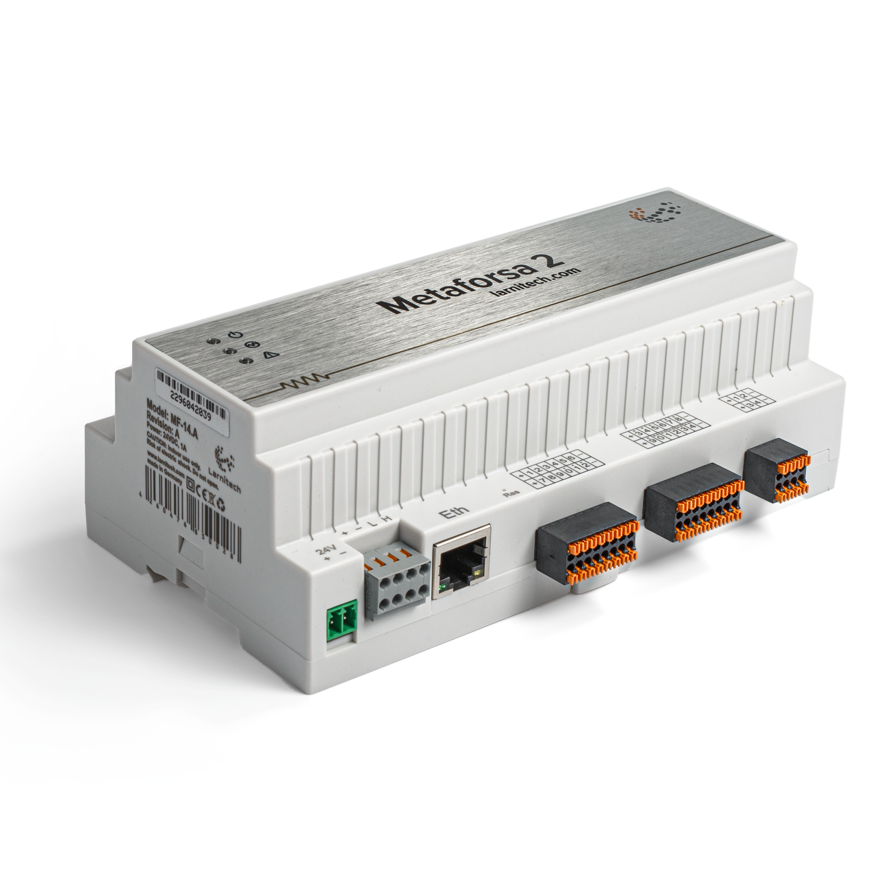
Splošni pogled modula je prikazan na Sl. 1

| 1 | — priključek za uporabo obremenitve |
| 2 | — priključek za uporabo zatemnitvenih sijalk |
| 3 | — priključek za napajanje |
| 4 | — Omrežni priključek Ethernet |
| 5-6 | — priključki za digitalne senzorje in gumbe/stikalne enote |
| 7 | — Vmesniški konektor OneWire (za digitalne senzorje) |
| 8 | — priključek za razširitveni modul. |
Pregled zunanjih priključkov naprave METAFORSA:
Na vrhu ohišja (sl. 1) je:
- konektor (1) — Priključek naprav;
- konektor (2) — Priključek zatemnitvenih svetilk;
Na dnu ohišja (sl. 1) je:
- konektor (3) — priključek za napajanje modula;
- priključek (4) — Ethernet omrežna povezava;
- konektorji (5-6) — štirje šesttočkovni konektorji za priklop digitalnih senzorjev – senzorji gibanja, puščanja, reed stikala in *senzorji tipke/stikalne enote;
- konektor (7) — povezava vodila digitalnih senzorjev OneWire;
- konektor (8) — priključek razširitvenega modula.
Fizična konfiguracija in dodelitev kontaktnih točk vsakega priključka sta prikazani v tabeli 2.
| Priključek | Kontakt | Dodelitev |
|---|---|---|
 |
1-10 | Uporaba obremenitve (luči, termični aktuatorji itd.) |
| D1-4, L, N | Uporaba obremenitve (svetilke za zatemnitev) | |
| Device status indicators | The module status indicators are described in table 3 | |
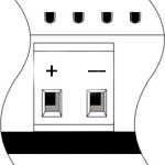 |
+24V GND |
+24V — napajanje modula z zunanjim 24 V napajalnikom GND — skupno |
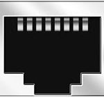 |
RJ45 | Priključek za LAN povezljivost |
| In1-12, In13-24 GND | Povezava krmilnih naprav (gumbi, magnetna reed stikala, senzorji gibanja ali puščanja): +12V — izhodna moč senzorja +12 V In1 … In24 — logični vhodi (0-12 V) GND — skupno | |
 |
OneWire | Digital sensors connection (temperature) VCC — sensors power supply output +5V OW1-OW4 — OneWire data buses GND — common |
 |
VCC GND L H |
Priključek zunanjih modulov za CAN-bus VСС — 24V izhod za napajanje zunanjih naprav GND — skupno L — CAN-L podatkovno vodilo H — CAN-H podatkovno vodilo |
| Indicator | Status | Description |
|---|---|---|
| Power | Power | |
| Power not available | ||
| Activity | Data communication | |
| Data communication not available | ||
| Error | No errors | |
| Communication error | ||
| Module overheat | ||
| Dimmer outputs module overload | ||
| Absence of power on dimmers, if in configuration |
Namestitev in montaža sistema
Preden priključite sistem, morate:
- postavite senzor in aktuatorje (če niso vnaprej nameščeni), nastavite senzorje in aktuatorje;
- site modul in napajalnik.
Opomba: Modul mora biti nameščen v bližini vira napajalne napetosti.
- Moč sklopa odklopnika mora ustrezati nosilnosti;
- Na modul ni mogoče priključiti nič drugega kot fazne vodnike, ničelna žica je priključena ločeno.
Tipična shema povezave modula METAFORSA MF-14.A je prikazana na sl. 3.

Povezava aktuatorjev
Povezava luči/električnega kontaktorja/ogrevalnega termičnega aktuatorja
 Sl. 4 |
Takšne aktuatorje, kot so luč, električni kontaktor, ogrevalni termični aktuator, je treba vklopiti na katerem koli od izhodov 1 – 10, nevtralno žico in ozemljitveno žico je treba priključiti neposredno na stikalno ploščo. Primer povezave je prikazan na Sl. 4. |
Priključitev visokoobremenjene naprave
 |
Priporočeni kontaktorji:
|
Priključitev enopolnega ventila za dovod vode/plina
| Pozor: Pred priključitvijo električne energije na obremenitev se prepričajte, da je izhodna konfiguracija modula METAFORSA pravilna. Napačna konfiguracija ali napačna povezava lahko povzroči okvaro modula in/ali okvaro opreme, povezane z njim, in celo požar. | |
 Sl. 5 |
Enopolni ventil za dovod vode/plina je priključen na katerega koli od izhodov 1 – 10, (nevtralna žica in ozemljitvena žica sta priključena neposredno na stikalno ploščo. Primer povezave je prikazan na sl.5). |
Priključitev dvopolnega ventila za dovod vode/plina
| Pozor: Pred priključitvijo napajanja na ventil je treba zagotoviti, da je izhodna konfiguracija modula METAFORSA pravilna. Nepravilna konfiguracija lahko povzroči istočasno uporabo napetosti na obeh kanalih ventila, kar lahko povzroči okvaro modula in/ali okvaro nanj povezane opreme in celo požar. | |
 Sl. 6 |
Dve sosednji kontaktni točki (na primer 3, 4) se uporabljata za priključitev dvopolnega ventila za dovod vode/plina; v teh pogojih sta nevtralna in ozemljitvena žica priključena neposredno na stikalno ploščo. Primer povezave je prikazan na Sl.6. |
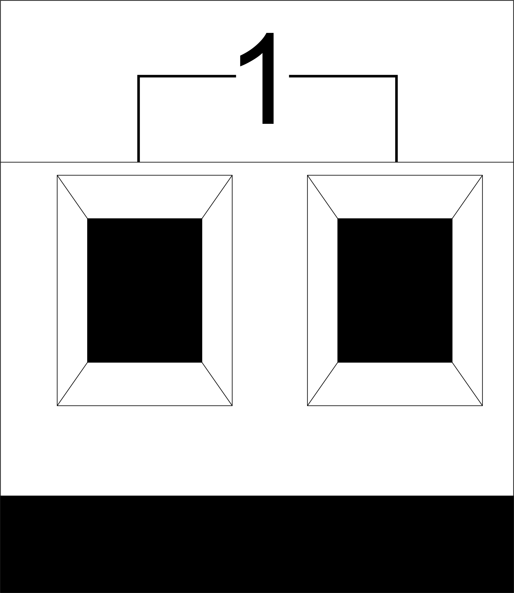
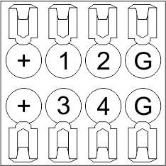
Priključitev enopolnega pogona vrat
| Caution: Before applying power to the module, you should properly configure access to the application. The contacts incorrectly configured can result in the module failure and/or failure of the equipment connected to it, and even a fire.
| |
 Fig. 7 |
Any contact point (for example, 3) is used to connect the single-pole gate drive controllers. The example of connection is shown in Fig.7. |
Connection of double-pole gate actuator
| Caution: Before applying power to the module, you must properly configure the outputs in the application. The contacts configured incorrectly can lead to simultaneous power supply to both channels, resulting in the module failure and/or failure of the equipment connected to it, and even a fire.
| |
 Fig. 8 |
Two adjacent contact points (for example, 3, 4) should be used to connect the double-pole gate drive controller. The example of connection is shown in Fig.8. |
Connection of curtain/jalousie/shutter actuator with 220V force control
| Caution: Before applying power to the module, you must properly configure the outputs in the application. The contacts configured incorrectly can lead to simultaneous power supply to both channels, resulting in the module failure and/or failure of the equipment connected to it, and even a fire.
| |
 Fig. 9 |
Two adjacent contact points (for example, 3, 4) should be used to connect the curtain/jalousie/rolladens actuator, in these conditions the neutral wire and the ground wire are connected directly to the switchboard. The example of connection is shown in Fig.9. |
Connection of curtain/jalousie/shutter actuator with low-voltage control
| Caution: Before applying power to the module, you must properly configure the outputs in the application. The contacts configured incorrectly can lead to simultaneous power supply to both channels, resulting in the module failure and/or failure of the equipment connected to it, and even a fire.
| |
 Fig. 10 |
Two adjacent contact points (for example, 3, 4) should be used to connect the curtain/jalousie/rolladens actuator with low-voltage control. The example of connection is shown in Fig.10. |
Connection of sensing elements/switches/buttons
Connection of motion sensors
The motion sensors should be connected to any free input in1-in24; in these conditions their power is connected to the contact points of +12V and GND of the relevant group. The example of connection is shown in Fig.11.

Fig. 11
Connection of FW-WL.A leakage sensors
FW-WL.A leakage sensors are connected to any free input in1 – in24, in these conditions the power should be connected to +12V and GND points of the relevant group. The example of connection is shown in fig. 12.
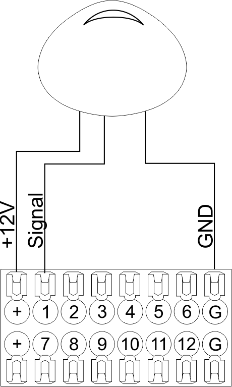 Fig12 |
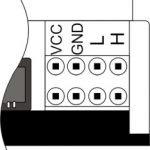
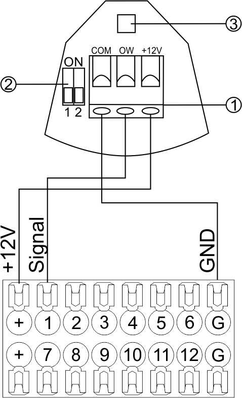 Fig13 |
Configuration and connection of the FW-WL.A sensor 1. Terminals:
- +12V — sensor power is connected to the contact point of METAFORSA “+12V”;
- OW — sensor pickup signal;
- GND — common, connected to GND contact of METAFORSA.
2. Sensor preset switch (optionally):
- 1 — sensor sensitivity (ON – high, OFF – low);
- 2 — indicator colour setting (ON – blue, OFF – green).
3. LED status indicator.
Connection of buttons/switches/magnetic reed switches
Buttons and reed switches are connected to any free input in1-in24, while their second contact point is connected to GND point of the relevant METAFORSA module group, + 12V power outputs – not in use. The example of connection is shown in Fig. 14-15.
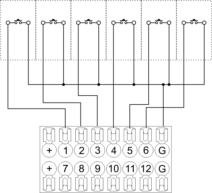 Fig14 connection of buttons/switching units |
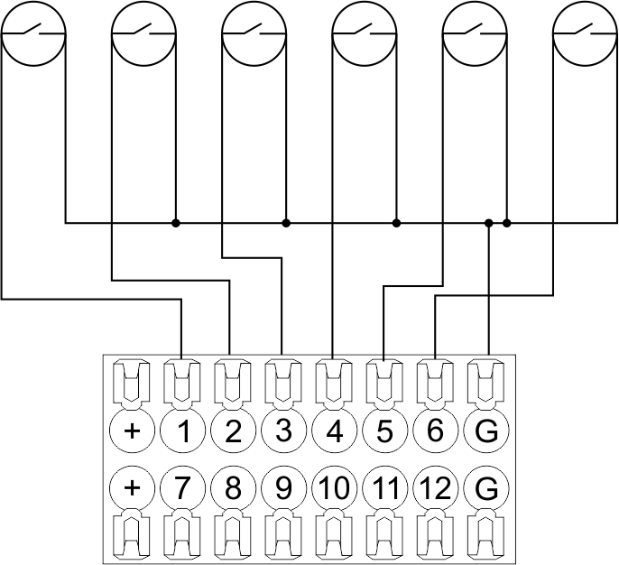 Fig15 connection of the magnetic reed switches (window/door position sensors) |
Connection of digital sensors
The OW adapter (Fig. 16a) is supplied along with METAFORSA module with the possibility to connect up to 8 digital sensors to it. In these conditions, several devices can be connected to one channel (Fig. 16b). The connected sensors are detected automatically and do not require any original setting.
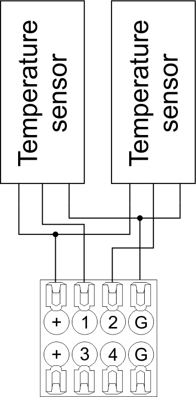 Fig16 a |
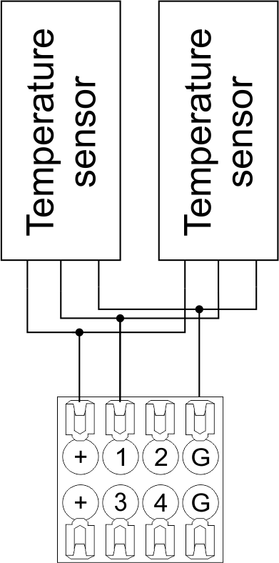 Fig16 b |
Configuration and connection of the OW adapter
Connection of auxiliary equipment.
Expansion modules include Larnitech equipment connected through the CAN-bus. Such equipment includes: dimmers, RGB-backlit control modules, multimode sensors, etc. The equipment connected to the expansion port is defined automatically and does not require any preset tuning. Connector contact pin assignment is defined in Table 4. The example of connection is shown in Fig. 17.
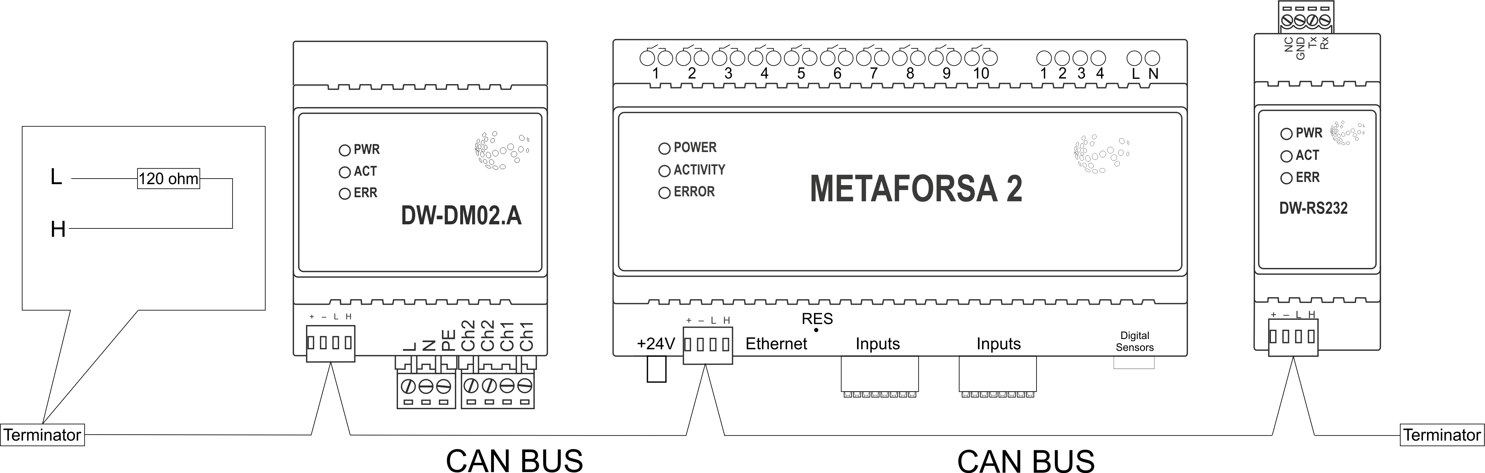
|
| Caution! The 120 ohm terminating resistors should be installed at the end connectors between L and H contact points of CAN-bus. Ensure the connection is correct. The incorrect connection may cause sensor and/or module malfunction. |
Module installation and connection procedure
- Install the module in the switchboard on the DIN-rail and fix it with the special latch on the module base.
- Fasten the supply unit on the left side of the module.
- Connect the connector (4) having the noise filter pre-installed which is supplied complete with the module.
- Connect the connectors (5), (6).
- Connect the connectors (1), (2).
- Connect the connector (3).
- Apply power to the supply unit of METAFORSA module.
- Wait until the module is loaded, then configure it in accordance with the System Setup Instructions.
- Apply power to the connectors (1), (2).
- Check all equipment for proper operation.
METAFORSA module shut-off and deinstallation procedure
- De-energize the module by disconnecting the circuit breaker assembly of the load power supply and METAFORSA module supply unit. Verify the voltage is absent on the terminals (1), (2) of the connector wires and on the input terminals of the supply unit.
- Disconnect the load power supply connectors (1), (2).
- Disconnect the connector (3).
- Disconnect the connectors (4)-(6).
- Remove the module from the DIN-rail, releasing the latch at the bottom of the module base.
Hardware setup
To configure and control METAFORSA SMART HOUSE, you must install Larnitech software on your smartphone or tablet, which is available in App Store and Play Market. After installation, follow the System Setup Instructions.
Fault diagnostics and handling
The following are some possible faults and ways of fault handling. If you have any difficulty, or face the fault undeclared here, please contact the Technical Support: [1] or [support@larnitech.com]. There are also some tips in the FAQ section at our website [2].
The actuators do not operate:
- ensure the outputs are properly configured in the application (see System Setup Instructions);
- check the connection is correct in accordance with table 2 and paragraph 3.6;
- ensure the power is supplied to the input power contact , i.e. all circuit breaker assembly are ON.
- verify the operability of the connected equipment.
The module is off, indication absent:
- check the connection to 24V supply unit as shown in table 2 (contacts pin assignment);
- check the connection of the supply unit to 220V power mains, the indicator should be ON.
Network connection fault:
- ensure the Ethernet cable is properly wired and connected to the connector;
- ensure the LED status indicators are ON on the Ethernet connector;
- check the LAN configuration is correct, Ethernet cable loops are absent;
- METAFORSA module and the device you are connecting from are in the same network.
hold integer 0-10000 1-10 by default hold is the same as runtime hold is the bridging time in miliseconds, is used for gate and jalousie, lock; Example: hold=3500
The sensors do not operate:
- ensure the inputs are properly configured in the application (System Setup Instructions);
- check the connection is correct in accordance with table 2 and paragraph 3.7;
- ensure the METAFORSA module is ON: circuit breaker assembly is closed, indication on the supply unit is ON, the module indication corresponds to the operating status – table 3;
- check the power supply availability on the sensors;
- check the integrity of lines laid to the sensors.
The auxiliary equipment does not operate:
- check the connection is correct in accordance with table 2 and paragraph 3.8-9;
- ensure the METAFORSA module is ON: circuit breaker assembly is closed, indication on the supply unit is ON, the module indication corresponds to the operating status – table 3;
- check the integrity of the CAN lines, voltage supply on the modules.
HW Settings
| Name | Type, range | SUBID | Default | Description |
|---|---|---|---|---|
| runtime | integer 0-100 | 1-10 | 15 | runtime is the open/close time in seconds, is used for jalousie, gate, valve(2 pole);
|
| runtimeopen | integer 0-60000 | Blinds subId | Runtimeopen is the open time in milliseconds, is used for blinds; Example: runtimeopen=15000 | |
| runtimeclose | integer 0-60000 | Blinds subId | Runtimeclose is the close time in milliseconds, is used for blinds; Example: runtimeclose=15000 | |
| hold | integer 0-10000 | 1-10 | 500 | hold is the bridging time in milliseconds, is used for gate and jalousie (by default hold is the same as runtime for jalousie and gate), lock; Example: hold=3500 |
| def | string 'ON' | 1-10 | 'OFF' | def is the element status is set after restart, is used for lamp, heating, valve(1 pole); Example: def='ON' |
| stop | Char ‘R’ | 1-7 | – | (for 2-pole gate and blinds) If it is declared then by Stop command during the motion, the same impulse appears as it was at the beginning of the motion. Pole, an which the stop-impules is formed, is defined by the parameter Stop value. If it is ‘r’ or ‘R’ then stop-impulse is produced on the opposite to the start-impulse pole. If any other value is delcared (e.g., ‘d’ ) then the stop-impulse is on the same pole. If a Runtime passed after the beginning of the motion then the stop-impulse is not formed. Example: stop=’r’ |
| out | char[10] | 98 | 'LLLLHHHHP-' | Each char is responsible for the type of a particular channel
Example: out='LLB-G-V-W-' |
| dm | char[4] | 98 | ‘LLLL’ | Each char is responsible for the type of a particular channel
Example: dm=’skl-‘ |
| def | integer 0-250 | 11-14 | 100 | The default brightness level in case of a power reset (1..250). Example: def=250 |
| min | integer 0-100 | 11-14 | 0 | Minimum dimming level, example: min=10 |
| max | integer 0-100 | 11-14 | 100 | Maximum dimming level, example max=95 |
| start | integer 0-100 | 11-14 | 0 | The Start function is used for lamps that lack the minimal voltage to get turned on. If the set value is lower than the start value, the lamp is turned on at the start value and them the light is dimmed down to the set level. Example: start=60 |
| force | integer 0-100 | 11-14 | 10 | Time duration of the starting value (measured in milliseconds). Example: force=20 |
| runtime | integer 0-60000 | 11-14 | 1000 | Runtime is the speed of changing the brightness from ‘min’ to ‘max’ (measured in milliseconds). Example: runtime=1000 |
| offset | integer (+/- 0…39) | 39-46 | '0' | sensor values offset; For example, offset is -3.8 :
Example: hw="offset='-3.8'" |
| in | char[24] | 98 | 'BBBBBBBBBBBBMMMLLLKKKKKK' | Each char is responsible for the type of a particular channel
Example: in='MMMMMMMMMMMMLLLLLLLLLLLL' 12 motion sensors and 12 leak-sensors; in='BBBBBBBBSSSSSSBBBBSSSSSS' 12 buttons; 12 switches. |
 1<item addr="339:1" auto-period="600" cfgid="40" hw="def='ON'" name="Lamp" type="lamp" uniq_id="3779">
 2<item addr="339:2" cfgid="40" hw="def='ON'" name="Radiator" type="valve-heating" uniq_id="3780">
 3    <automation name="Eco" temperature-level="16" uniq_id="3781"/>
 4    <automation name="Comfort" temperature-level="22" uniq_id="3782"/>
 5    <automation name="Hot" temperature-level="25" uniq_id="3783"/>
 6</item>
 7<item addr="339:3" cfgid="40" hw="runtime=9" name="Jalousie" sub-type="120" type="jalousie" uniq_id="32"/>
 8<item addr="339:5" cfgid="40" hw="runtime=13" name="Gate" sub-type="120" type="gate" uniq_id="3784"/>
 9<item addr="339:7" cfgid="40" hw="hold=4600" name="Gate" sub-type="120" type="gate" uniq_id="3785"/>
10<item addr="339:8" cfgid="40" hw="runtime=10" name="Valve" type="valve" uniq_id="3786"/>
11<item addr="339:11" cfgid="40" name="Motion" type="motion-sensor" uniq_id="17"/>
12<item addr="339:12" cfgid="40" name="Motion" type="motion-sensor" uniq_id="18"/>
13<item addr="339:13" cfgid="40" name="Motion" type="motion-sensor" uniq_id="19"/>
14<item addr="339:16" cfgid="40" name="Leak" type="leak-sensor" uniq_id="21"/>
15<item addr="339:17" cfgid="40" name="Leak" type="leak-sensor" uniq_id="41"/>
16<item addr="339:19" cfgid="40" name="Switch" type="switch" uniq_id="22"/>
17<item addr="339:20" cfgid="40" name="Switch" type="switch" uniq_id="23"/>
18<item addr="339:21" cfgid="40" name="Switch" type="switch" uniq_id="24"/>
19<item addr="339:22" cfgid="40" name="Switch" type="switch" uniq_id="25"/>
20<item addr="339:23" cfgid="40" name="Door" type="door-sensor" uniq_id="26"/>
21<item addr="339:24" cfgid="40" name="Door" type="door-sensor" uniq_id="27"/>
22<item addr="339:25" cfgid="40" name="Door" type="door-sensor" uniq_id="28"/>
23<item addr="339:26" cfgid="40" name="Door" type="door-sensor" uniq_id="29"/>
24<item addr="339:30" cfgid="40" name="Temperature" type="temperature-sensor" uniq_id="3772"/>
25<item addr="339:31" cfgid="40" name="Temperature" type="temperature-sensor" uniq_id="3773"/>
26<item addr="339:32" cfgid="40" name="Temperature" type="temperature-sensor" uniq_id="3774"/>
27<item addr="339:33" cfgid="40" hw="offset='-10.8'" name="Temperature" type="temperature-sensor" uniq_id="3775"/>
28<item addr="339:34" cfgid="40" hw="offset='25.1'" name="Temperature" type="temperature-sensor" uniq_id="3776"/>
29<item addr="339:35" cfgid="40" name="Temperature" type="temperature-sensor" uniq_id="3777"/>
30<item addr="339:36" cfgid="40" name="Temperature" type="temperature-sensor" uniq_id="3778"/>
31<item addr="339:98" cfgid="40" hw="out='LHB-G-XV--' in='MMM--LL-BBBBKKKK'" name="Temperature" system="yes" type="temperature-sensor" uniq_id="30"/>