Metaforsa2 MF-14
| MF-14 | |||||||||||||
|---|---|---|---|---|---|---|---|---|---|---|---|---|---|
 | |||||||||||||
| |||||||||||||
| |||||||||||||
| |||||||||||||
Вступ
Інструкція з монтажу METAFORSA SMART HOUSE описує процедуру встановлення, збирання, експлуатації та налаштування системи. Під час роботи з системою обов'язково дотримуйтеся всіх вимог, викладених у цьому посібнику. Невиконання цих вимог може призвести до пошкодження пристрою, його відмови, ураження електричним струмом, пожежі та інших непередбачених ситуацій. Виробник залишає за собою право вносити зміни до цієї інструкції без попереднього повідомлення. Цей посібник є невід'ємною частиною системи і повинен знаходитися у кінцевого користувача.
Особливості
- Підтримка 10 універсальних виходів:
- Світло
- Клапани опалення NC/NO
- Жалюзі
- 1 або 2-полюсні ворота
- 1 або 2-полюсні клапани
- Замки NC/NO
- Фанкойли
- 4 виходи дімування
- 24 дискретні входи, які підтримують:
- Кнопки
- Перемикачі
- Геркони
- Датчики протікання
- Датчики руху
- 4 цифрові входи для підключення до 8 датчиків температури
- Порт розширення
- Реле з контактами AgSnO2, розрахованими на пусковий струм 80А 20мс
- Підключення до хмари та керування всіма системами будинку
- Голосове управління (Siri, Alexa, Google Home)
- Система плагінів дозволяє розширювати можливості системи (наприклад, інтеграція з освітлювальними приладами Satel, Philips Hue, IKEA)
- Безпека від несанкціонованого втручання забезпечується за допомогою шифрування RSA/AES256
- Пуш-повідомлення від системи на телефон (також можливе отримання через месенджери Telegram та Viber)
- Історія (зберігаються дані лічильника за 1 рік)
- Plug and play (можливість швидкого та зручного розширення системи)
- Регулярні оновлення системи
- Велика база скриптів, що постійно оновлюється, щоб задовольнити всі ваші потреби
- Автоматичне щоденне резервне копіювання через хмару з можливістю відновлення початкової конфігурації
- Відкритий API (що дозволяє інтегрувати Larnitech в інші системи)
- Інтерактивний і зручний веб-інтерфейс LT SETUP, доступний для розширеної конфігурації
- Повністю готовий до встановлення комплект системи "Розумний дім
Вимоги техніки безпеки
Щоб уникнути ризику пожежі, ураження електричним струмом, пошкодження системи та/або отримання травми, установку й збірку системи слід виконувати відповідно до наведених нижче інструкцій:
- всі роботи по підключенню повинні виконуватися без електроживлення;
- використовуйте відповідні інструменти та засоби індивідуального захисту від ураження електричним струмом;
- не використовуйте пошкоджені кабелі, дроти та роз'єми;
- не допускайте згинання кабелів та проводів;
- не перетискайте і не перегинайте кабелі та дроти, застосовуючи надмірну силу. В іншому випадку внутрішні провідники кабелю та проводів можуть бути оголені або зламані;
- не використовуйте для підключення розетку з поганими контактами;
- не перевищуйте граничні параметри навантаження, зазначені в цьому посібнику;
- перетин жил кабелю живлення повинен відповідати технічним вимогам щодо граничної густини струму, типу ізоляції та матеріалу жил. Замалий перетин може призвести до перегріву кабелю та пожежі.
При роботі з системою після подачі напруги НІКОЛИ:
- підключати/відключати роз'єми;
- розкривати модулі та датчики.
Конфігурація та призначення системи
Призначення системи
METAFORSA SMART HOUSE - це готове рішення для автоматизації житлових і комерційних приміщень, готельних комплексів, яке включає в себе найбільш необхідні функції "розумного будинку".
Пристрій має 10 каналів керування, 4 канали дімування, 24 канали вхідних датчиків і порт для підключення цифрових датчиків.
| Універсальні виходи можна використовувати для керування: | Універсальні входи дозволяють підключати: |
|---|---|
| Освітлення | Кнопки/перемикачі |
| Гніздові роз'єми | Магнітні герконові вимикачі |
| Датчики руху | |
| Датчики протікання | |
| Клапани водопостачання/опалення |
Порт підключення цифрових датчиків
The digital sensors connection port allows you to connect a variety of digital sensors, such as temperature sensors, ambient light, humidity and other.
Порт розширення
The expansion port allows you to upgrade the system by connecting auxiliary equipment, such as the control module for LED lighting, dimming, metering devices and other elements.
The package, which is completely ready-to-install, includes the basic hardware and software.
Вміст пакування
The package comes standard with:
| Mainframe METAFORSA MF-14.А | 1 pc |
| Power supply unit MEANWELL DR-15-12 | 1 pc |
| Motion sensor CW-MSD | 3 pcs |
| Leakage sensor FW-WL.A | 2 pcs |
| Temperature-sensitive element FW-TS.A | 4 pcs |
| Magnetic reed switch (window/door position sensor) | 4 pcs |
| Ethernet-cable noise filter | 1 pc |
| Power supply cord | 1 pc |
| Manual | 1 pc |
Основні технічні характеристики системи
Основні технічні характеристики та характеристики модуля METAFORSA MF-14.A наведені в таблиці 1
| Технічні характеристики | Значення |
|---|---|
| 'Вихідні порти' | |
| Кількість релейних каналів | 10 |
| Кількість релейних груп | 10 |
| Кількість каналів диммування | 4 |
| Напруга комутації | 0-250 В змінного/постійного струму |
| Пікове навантаження (один канал) | 16А |
| Пікове навантаження (прилад) | 160А |
| Максимальне навантаження на канал диммування | 0,5 A (110 Вт при 220 В) |
| Тип диммера | MOSFET |
| Тип навантаження диммера | R,C |
| Тип затемнення | задній край |
| Тип підключення кабелю живлення | конектор |
| Допустимий перетин кабелю живлення для підключення до розетки: одножильний кабель багатожильний кабель багатожильний кабель з наконечником |
0,5 … 4 мм2 0,5 … 4 мм2 0,5 … 2,5 мм2 |
| 'Вхідні порти' | |
| Кількість дискретних входів | 24 |
| Кількість цифрових входів | 4 |
| Максимальний струм на роз'ємах постійної напруги | 50 мА |
| 'Інше' | |
| Робоча температура навколишнього середовища | 0 … +45°С |
| Температура зберігання/транспортування | -20 … +60°С |
| Допустима вологість | 0 … 95% (без конденсації) |
| Електропостачання | 12 … 27,5 В постійного струму 24 В, 0,75 A рекомендовано |
| Максимальний попит | 0,5А |
| Доступні інтерфейси | Ethernet, CAN, OneWire |
| Тип автобуса | CAN (4-провідний) |
| CAN (4-провідний) | 800 м* (кручена пара 5 категорії) |
| Тип проводу CAN | FTP Cat 5E |
| Тип підключення CAN | роз'єм |
| Максимальна довжина цифрової лінії | 30 м |
| Цифрова лінія Wirde типу | UTP/FTP Cat 5E |
| максимальна довжина локальної мережі | 100 м |
| Тип проводу LAN | UTP/FTP Cat 5E |
| Тип підключення LAN | Роз'єм RJ-45 |
| Габаритні характеристики | 9U, 156x110x58 мм |
| Матеріал оболонки | ABS пластик |
| Обшивка | IP40 |
| Тип установки обладнання | DIN-рейка (EN 60715) |
| Вага | 400 г |
* – для довгих ліній потрібна установка додаткових блоків живлення; максимальна довжина лінії може бути зменшена різними факторами перешкод
General structure of the System
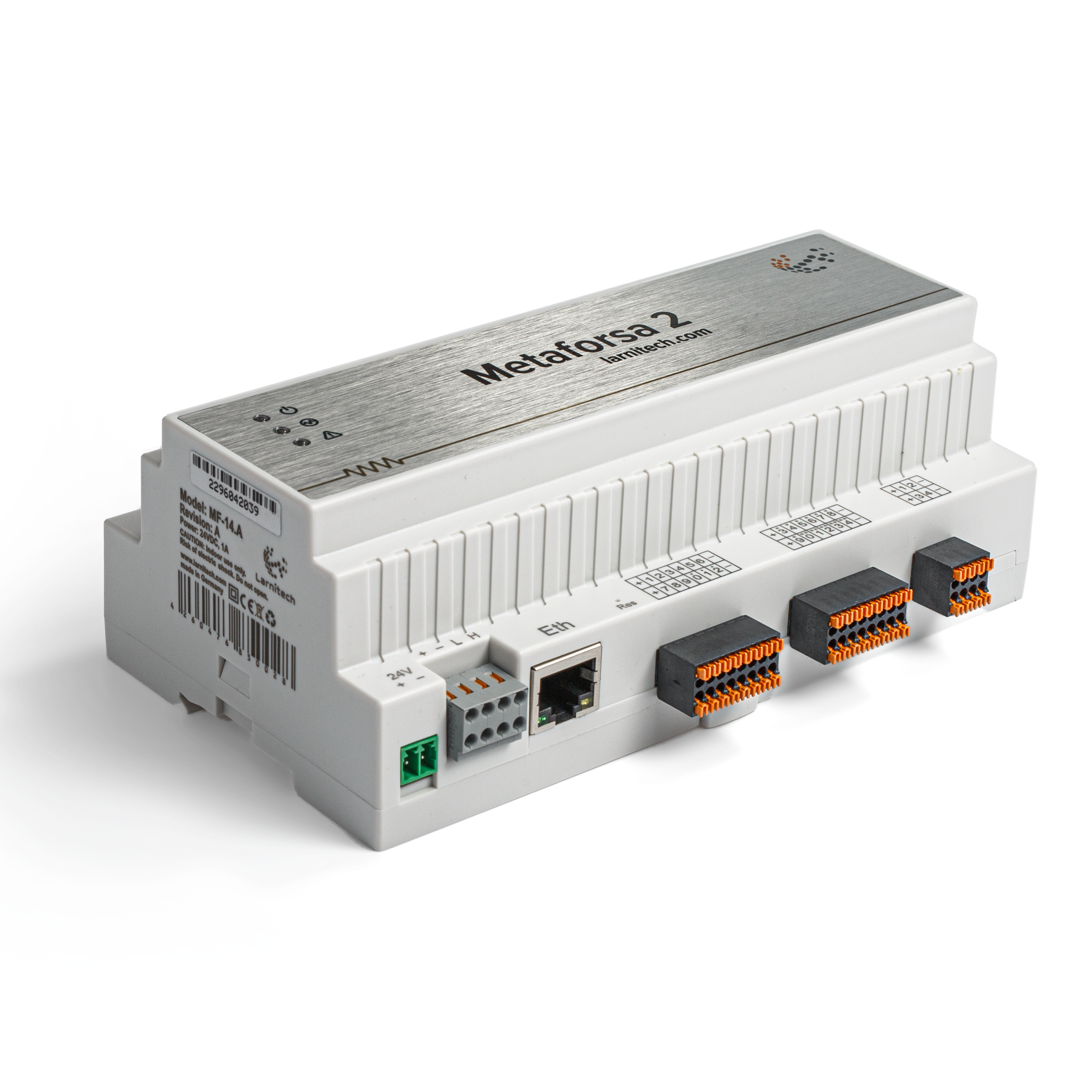
Module general view is shown in fig. 1

| 1 | — роз'єм для додатка навантаження |
| 2 | — роз'єм для підключення диммерів |
| 3 | — роз’єм живлення |
| 4 | — Мережевий роз'єм Ethernet |
| 5-6 | — роз’єми для цифрових датчиків і кнопок/комутаторів |
| 7 | — Роз’єм інтерфейсу OneWire (для цифрових датчиків) |
| 8 | — роз’єм для підключення модуля розширення. |
Огляд зовнішніх роз'ємів пристрою METAFORSA:
У верхній частині корпусу (мал. 1) є:
- роз'єм (1) — для підключення пристроїв;
- роз'єм (2) — для підключення диммованих ламп;
У нижній частині корпусу (рис. 1) є:
- роз'єм (3) — для підключення блоку живлення;
- роз'єм (4) — для підключення до мережі Ethernet;
- роз’єми (5-6) — чотири шеститочкові роз’єми для підключення цифрових датчиків – датчиків руху, протікання, герконів та датчиків *кнопок/перемекачів;
- роз'єм (7) — для підключення шини цифрових датчиків OneWire;
- роз'єм (8) — для підключення модуля розширення.
Фізична конфігурація та призначення контактів кожного роз'єму показані в таблиці 2.
| Роз'єм | ! Контакт | ! Призначення | ! |
|---|---|---|---|
 |
1-10 | Навантаження (лампи освітлення, термоприводи і т.д.) | |
| D1-4, L, N | Навантаження (дімування ламп) | ||
| Індикатори стану пристрою | Індикатори стану модуля описані в таблиці 3 | ||
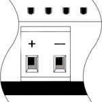 |
+24В GND |
+24В - живлення модуля від зовнішнього джерела живлення 24 В GND - загальна | |
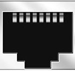 |
RJ45 | Роз'єм для підключення до локальної мережі | |
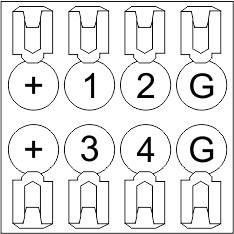
| In1-12, In13-24 GND | Підключення контрольних пристроїв (кнопки, магнітні геркони, датчики руху або протікання): +12V — вихід живлення датчика +12 В In1 … In24 — логічні входи (0-12 В) GND — загальний | ||
 |
OneWire | Підключення цифрових датчиків (температура) VCC — вихід живлення датчиків +5В OW1-OW4 — шини даних OneWire GND — загальний | |
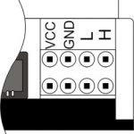 |
VCC GND L H |
Підключення зовнішніх модулів для CAN-шини VСС — вихід 24В для живлення зовнішніх пристроїв GND — загальний L — шина даних CAN-L H — шина даних CAN-H | |
| Indicator | Status | Description |
|---|---|---|
| Power | Power | |
| Power not available | ||
| Activity | Data communication | |
| Data communication not available | ||
| Error | No errors | |
| Communication error | ||
| Module overheat | ||
| Dimmer outputs module overload | ||
| Absence of power on dimmers, if in configuration |
Установка та збірка системи
Перед підключенням системи необхідно:
- Встановіть датчики та виконавчі механізми (якщо вони не встановлені), налаштуйте датчики та виконавчі механізми;
- встановіть модуль і блок живлення.
Примітка: Модуль повинен бути встановлений поблизу джерела живлення.
- 'Потужність вузла автоматичного вимикача повинна відповідати навантажувальній здатності;
- 'До модуля не можна підключати нічого, крім фазних проводів, нульовий провід підключається окремо.'
Типова схема підключення модуля METAFORSA MF-14.A наведена на мал. 3.

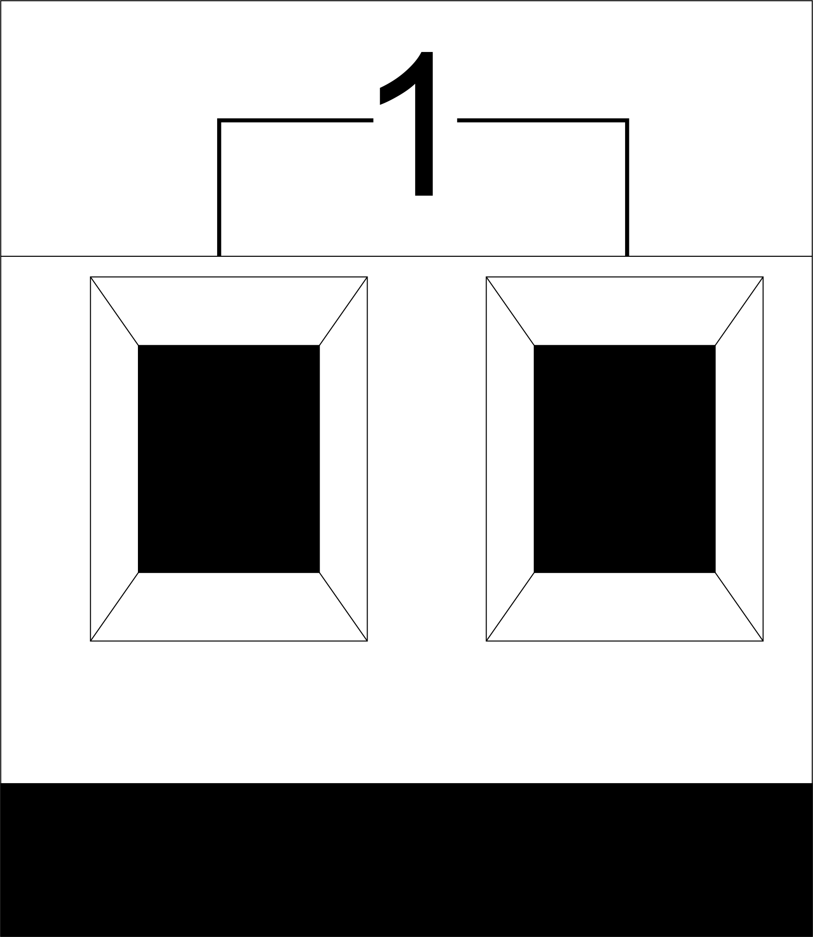
Підключення приводів
Підключення освітлення/електроконтактора/термоприводу опалення
 Fig. 4 |
Такі виконавчі пристрої, як світло, електричний контактор, нагрівальний термопривід, слід вмикати на будь-який з виходів 1 - 10, нульовий провід і провід заземлення слід підключати безпосередньо до розподільного щита. Приклад підключення показано на рис.4. |
Підключення пристроїв з високим навантаженням
 |
Рекомендовані контактори:
|
Connection of single-pole water/gas supply valve
| Увага! Перед подачею живлення на навантаження переконайтеся, що конфігурація виходу модуля METAFORSA є правильною. Неправильна конфігурація або неправильне підключення може призвести до виходу модуля з ладу та/або несправності підключеного до нього обладнання і навіть до пожежі. | |
 Fig. 5 |
Однополюсний клапан подачі води/газу підключається до будь-якого з виходів 1 - 10, нульовий провід і провід заземлення підключаються безпосередньо до розподільного щита. Приклад підключення показаний на Рис.5. |
Connection of double-pole water/gas supply valve
| Увага! Перед подачею живлення на клапан необхідно переконатися, що конфігурація виходу модуля METAFORSA є правильною. Неправильна конфігурація може призвести до одночасної подачі напруги на обидва канали клапана, що може стати причиною виходу з ладу модуля та/або підключеного до нього обладнання і навіть пожежі. | |
 Fig. 6 |
Для підключення двополюсного клапана подачі води/газу використовуються дві сусідні контактні точки (наприклад, 3, 4); в цих умовах нульовий провід і провід заземлення підключаються безпосередньо до розподільного щита. Приклад підключення показаний на мал.6. |
Підключення однополюсного приводу воріт
| Увага! Перед подачею живлення на модуль слід правильно налаштувати доступ до застосунку. Неправильне налаштування контактів може призвести до виходу модуля з ладу та/або несправності підключеного до нього обладнання і навіть до пожежі.
| |
 Fig. 7 |
Будь-яка контактна точка (наприклад, 3) використовується для підключення однополюсних контролерів приводу воріт. Приклад підключення показано на Рис.7. |
Підключення двополюсного приводу воріт
| Увага! Перед подачею живлення на модуль необхідно правильно налаштувати виходи в застосунку. Неправильно налаштовані контакти можуть призвести до одночасної подачі живлення на обидва канали, що призведе до виходу модуля з ладу та/або несправності підключеного до нього обладнання і навіть до пожежі.
| |
 Fig. 8 |
Для підключення двополюсного контролера приводу воріт слід використовувати дві сусідні контактні точки (наприклад, 3, 4). Приклад підключення показано на мал.8. |
Підключення приводу штор/жалюзі/жалюзі з керуванням навантаженням 220В
| Увага! Перед подачею живлення на модуль необхідно правильно налаштувати виходи в застосунку. Неправильно налаштовані контакти можуть призвести до одночасної подачі живлення на обидва канали, що призведе до виходу модуля з ладу та/або несправності підключеного до нього обладнання і навіть до пожежі.
| |
 Fig. 9 |
Для підключення приводу штор/жалюзі/ролетів слід використовувати дві сусідні контактні точки (наприклад, 3, 4), при цьому нульовий провід і провід заземлення підключаються безпосередньо до розподільного щита. Приклад підключення показаний на мал.9. |
Підключення приводу штор/жалюзі/жалюзі з низьковольтним керуванням
| Caution: Before applying power to the module, you must properly configure the outputs in the application. The contacts configured incorrectly can lead to simultaneous power supply to both channels, resulting in the module failure and/or failure of the equipment connected to it, and even a fire.
| |
 Fig. 10 |
Two adjacent contact points (for example, 3, 4) should be used to connect the curtain/jalousie/rolladens actuator with low-voltage control. The example of connection is shown in Fig.10. |
Connection of sensing elements/switches/buttons
Connection of motion sensors
The motion sensors should be connected to any free input in1-in24; in these conditions their power is connected to the contact points of +12V and GND of the relevant group. The example of connection is shown in Fig.11.

Fig. 11
Connection of FW-WL.A leakage sensors
FW-WL.A leakage sensors are connected to any free input in1 – in24, in these conditions the power should be connected to +12V and GND points of the relevant group. The example of connection is shown in fig. 12.
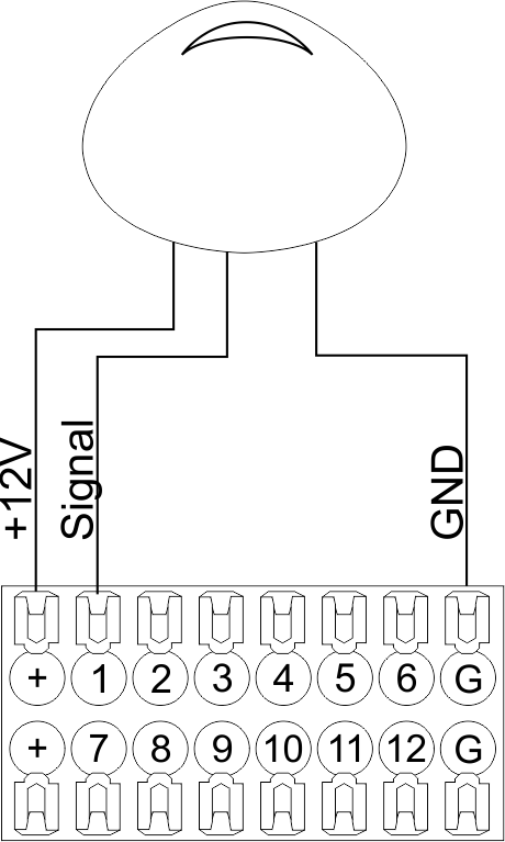 Fig12 |
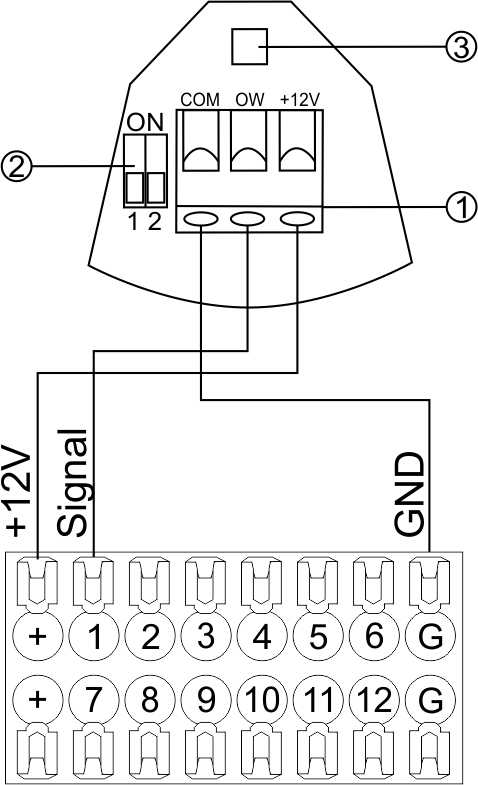 Fig13 |
Configuration and connection of the FW-WL.A sensor 1. Terminals:
- +12V — sensor power is connected to the contact point of METAFORSA “+12V”;
- OW — sensor pickup signal;
- GND — common, connected to GND contact of METAFORSA.
2. Sensor preset switch (optionally):
- 1 — sensor sensitivity (ON – high, OFF – low);
- 2 — indicator colour setting (ON – blue, OFF – green).
3. LED status indicator.
Connection of buttons/switches/magnetic reed switches
Buttons and reed switches are connected to any free input in1-in24, while their second contact point is connected to GND point of the relevant METAFORSA module group, + 12V power outputs – not in use. The example of connection is shown in Fig. 14-15.
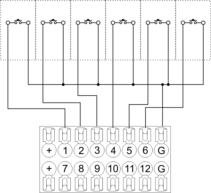 Fig14 connection of buttons/switching units |
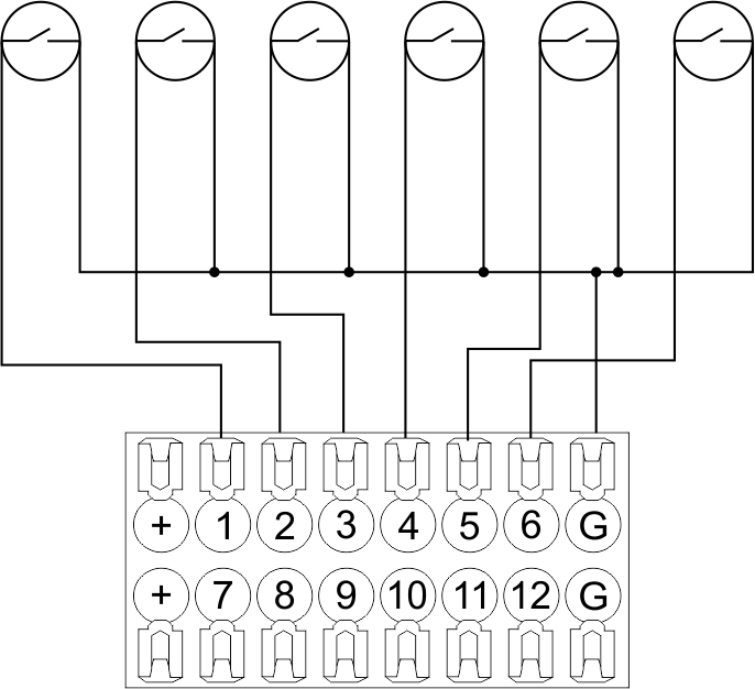 Fig15 connection of the magnetic reed switches (window/door position sensors) |
Connection of digital sensors
The OW adapter (Fig. 16a) is supplied along with METAFORSA module with the possibility to connect up to 8 digital sensors to it. In these conditions, several devices can be connected to one channel (Fig. 16b). The connected sensors are detected automatically and do not require any original setting.
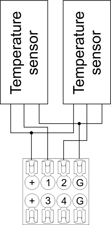 Fig16 a |
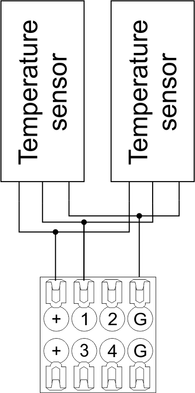 Fig16 b |
Configuration and connection of the OW adapter
Connection of auxiliary equipment.
Expansion modules include Larnitech equipment connected through the CAN-bus. Such equipment includes: dimmers, RGB-backlit control modules, multimode sensors, etc. The equipment connected to the expansion port is defined automatically and does not require any preset tuning. Connector contact pin assignment is defined in Table 4. The example of connection is shown in Fig. 17.
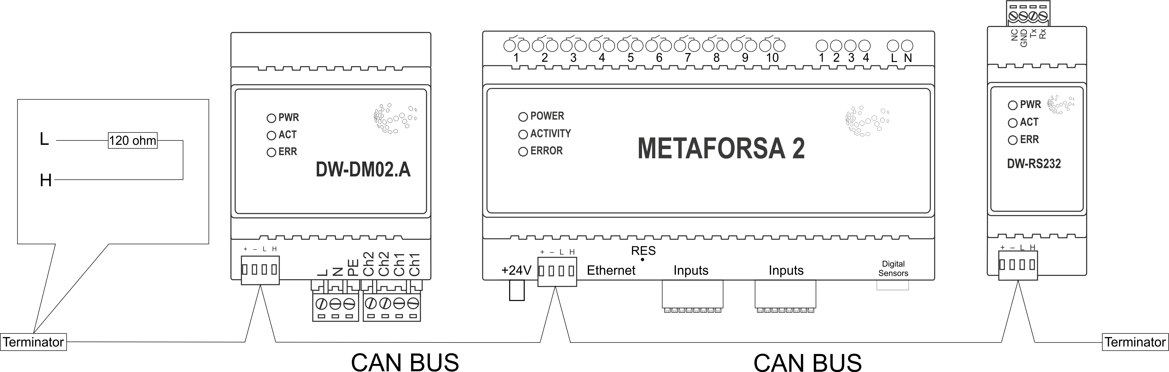
|
| Caution! The 120 ohm terminating resistors should be installed at the end connectors between L and H contact points of CAN-bus. Ensure the connection is correct. The incorrect connection may cause sensor and/or module malfunction. |
Module installation and connection procedure
- Install the module in the switchboard on the DIN-rail and fix it with the special latch on the module base.
- Fasten the supply unit on the left side of the module.
- Connect the connector (4) having the noise filter pre-installed which is supplied complete with the module.
- Connect the connectors (5), (6).
- Connect the connectors (1), (2).
- Connect the connector (3).
- Apply power to the supply unit of METAFORSA module.
- Wait until the module is loaded, then configure it in accordance with the System Setup Instructions.
- Apply power to the connectors (1), (2).
- Check all equipment for proper operation.
METAFORSA module shut-off and deinstallation procedure
- De-energize the module by disconnecting the circuit breaker assembly of the load power supply and METAFORSA module supply unit. Verify the voltage is absent on the terminals (1), (2) of the connector wires and on the input terminals of the supply unit.
- Disconnect the load power supply connectors (1), (2).
- Disconnect the connector (3).
- Disconnect the connectors (4)-(6).
- Remove the module from the DIN-rail, releasing the latch at the bottom of the module base.
Hardware setup
To configure and control METAFORSA SMART HOUSE, you must install Larnitech software on your smartphone or tablet, which is available in App Store and Play Market. After installation, follow the System Setup Instructions.
Fault diagnostics and handling
The following are some possible faults and ways of fault handling. If you have any difficulty, or face the fault undeclared here, please contact the Technical Support: [1] or [support@larnitech.com]. There are also some tips in the FAQ section at our website [2].
The actuators do not operate:
- ensure the outputs are properly configured in the application (see System Setup Instructions);
- check the connection is correct in accordance with table 2 and paragraph 3.6;
- ensure the power is supplied to the input power contact , i.e. all circuit breaker assembly are ON.
- verify the operability of the connected equipment.
The module is off, indication absent:
- check the connection to 24V supply unit as shown in table 2 (contacts pin assignment);
- check the connection of the supply unit to 220V power mains, the indicator should be ON.
Network connection fault:
- ensure the Ethernet cable is properly wired and connected to the connector;
- ensure the LED status indicators are ON on the Ethernet connector;
- check the LAN configuration is correct, Ethernet cable loops are absent;
- METAFORSA module and the device you are connecting from are in the same network.
hold integer 0-10000 1-10 by default hold is the same as runtime hold is the bridging time in miliseconds, is used for gate and jalousie, lock; Example: hold=3500
The sensors do not operate:
- ensure the inputs are properly configured in the application (System Setup Instructions);
- check the connection is correct in accordance with table 2 and paragraph 3.7;
- ensure the METAFORSA module is ON: circuit breaker assembly is closed, indication on the supply unit is ON, the module indication corresponds to the operating status – table 3;
- check the power supply availability on the sensors;
- check the integrity of lines laid to the sensors.
The auxiliary equipment does not operate:
- check the connection is correct in accordance with table 2 and paragraph 3.8-9;
- ensure the METAFORSA module is ON: circuit breaker assembly is closed, indication on the supply unit is ON, the module indication corresponds to the operating status – table 3;
- check the integrity of the CAN lines, voltage supply on the modules.
HW Settings
| Name | Type, range | SUBID | Default | Description |
|---|---|---|---|---|
| runtime | integer 0-100 | 1-10 | 15 | runtime is the open/close time in seconds, is used for jalousie, gate, valve(2 pole);
|
| runtimeopen | integer 0-60000 | Blinds subId | Runtimeopen is the open time in milliseconds, is used for blinds; Example: runtimeopen=15000 | |
| runtimeclose | integer 0-60000 | Blinds subId | Runtimeclose is the close time in milliseconds, is used for blinds; Example: runtimeclose=15000 | |
| hold | integer 0-10000 | 1-10 | 500 | hold is the bridging time in milliseconds, is used for gate and jalousie (by default hold is the same as runtime for jalousie and gate), lock; Example: hold=3500 |
| def | string 'ON' | 1-10 | 'OFF' | def is the element status is set after restart, is used for lamp, heating, valve(1 pole); Example: def='ON' |
| stop | Char ‘R’ | 1-7 | – | (for 2-pole gate and blinds) If it is declared then by Stop command during the motion, the same impulse appears as it was at the beginning of the motion. Pole, an which the stop-impules is formed, is defined by the parameter Stop value. If it is ‘r’ or ‘R’ then stop-impulse is produced on the opposite to the start-impulse pole. If any other value is delcared (e.g., ‘d’ ) then the stop-impulse is on the same pole. If a Runtime passed after the beginning of the motion then the stop-impulse is not formed. Example: stop=’r’ |
| out | char[10] | 98 | 'LLLLHHHHP-' | Each char is responsible for the type of a particular channel
Example: out='LLB-G-V-W-' |
| dm | char[4] | 98 | ‘LLLL’ | Each char is responsible for the type of a particular channel
Example: dm=’skl-‘ |
| def | integer 0-250 | 11-14 | 100 | The default brightness level in case of a power reset (1..250). Example: def=250 |
| min | integer 0-100 | 11-14 | 0 | Minimum dimming level, example: min=10 |
| max | integer 0-100 | 11-14 | 100 | Maximum dimming level, example max=95 |
| start | integer 0-100 | 11-14 | 0 | The Start function is used for lamps that lack the minimal voltage to get turned on. If the set value is lower than the start value, the lamp is turned on at the start value and them the light is dimmed down to the set level. Example: start=60 |
| force | integer 0-100 | 11-14 | 10 | Time duration of the starting value (measured in milliseconds). Example: force=20 |
| runtime | integer 0-60000 | 11-14 | 1000 | Runtime is the speed of changing the brightness from ‘min’ to ‘max’ (measured in milliseconds). Example: runtime=1000 |
| offset | integer (+/- 0…39) | 39-46 | '0' | sensor values offset; For example, offset is -3.8 :
Example: hw="offset='-3.8'" |
| in | char[24] | 98 | 'BBBBBBBBBBBBMMMLLLKKKKKK' | Each char is responsible for the type of a particular channel
Example: in='MMMMMMMMMMMMLLLLLLLLLLLL' 12 motion sensors and 12 leak-sensors; in='BBBBBBBBSSSSSSBBBBSSSSSS' 12 buttons; 12 switches. |
 1<item addr="339:1" auto-period="600" cfgid="40" hw="def='ON'" name="Lamp" type="lamp" uniq_id="3779">
 2<item addr="339:2" cfgid="40" hw="def='ON'" name="Radiator" type="valve-heating" uniq_id="3780">
 3    <automation name="Eco" temperature-level="16" uniq_id="3781"/>
 4    <automation name="Comfort" temperature-level="22" uniq_id="3782"/>
 5    <automation name="Hot" temperature-level="25" uniq_id="3783"/>
 6</item>
 7<item addr="339:3" cfgid="40" hw="runtime=9" name="Jalousie" sub-type="120" type="jalousie" uniq_id="32"/>
 8<item addr="339:5" cfgid="40" hw="runtime=13" name="Gate" sub-type="120" type="gate" uniq_id="3784"/>
 9<item addr="339:7" cfgid="40" hw="hold=4600" name="Gate" sub-type="120" type="gate" uniq_id="3785"/>
10<item addr="339:8" cfgid="40" hw="runtime=10" name="Valve" type="valve" uniq_id="3786"/>
11<item addr="339:11" cfgid="40" name="Motion" type="motion-sensor" uniq_id="17"/>
12<item addr="339:12" cfgid="40" name="Motion" type="motion-sensor" uniq_id="18"/>
13<item addr="339:13" cfgid="40" name="Motion" type="motion-sensor" uniq_id="19"/>
14<item addr="339:16" cfgid="40" name="Leak" type="leak-sensor" uniq_id="21"/>
15<item addr="339:17" cfgid="40" name="Leak" type="leak-sensor" uniq_id="41"/>
16<item addr="339:19" cfgid="40" name="Switch" type="switch" uniq_id="22"/>
17<item addr="339:20" cfgid="40" name="Switch" type="switch" uniq_id="23"/>
18<item addr="339:21" cfgid="40" name="Switch" type="switch" uniq_id="24"/>
19<item addr="339:22" cfgid="40" name="Switch" type="switch" uniq_id="25"/>
20<item addr="339:23" cfgid="40" name="Door" type="door-sensor" uniq_id="26"/>
21<item addr="339:24" cfgid="40" name="Door" type="door-sensor" uniq_id="27"/>
22<item addr="339:25" cfgid="40" name="Door" type="door-sensor" uniq_id="28"/>
23<item addr="339:26" cfgid="40" name="Door" type="door-sensor" uniq_id="29"/>
24<item addr="339:30" cfgid="40" name="Temperature" type="temperature-sensor" uniq_id="3772"/>
25<item addr="339:31" cfgid="40" name="Temperature" type="temperature-sensor" uniq_id="3773"/>
26<item addr="339:32" cfgid="40" name="Temperature" type="temperature-sensor" uniq_id="3774"/>
27<item addr="339:33" cfgid="40" hw="offset='-10.8'" name="Temperature" type="temperature-sensor" uniq_id="3775"/>
28<item addr="339:34" cfgid="40" hw="offset='25.1'" name="Temperature" type="temperature-sensor" uniq_id="3776"/>
29<item addr="339:35" cfgid="40" name="Temperature" type="temperature-sensor" uniq_id="3777"/>
30<item addr="339:36" cfgid="40" name="Temperature" type="temperature-sensor" uniq_id="3778"/>
31<item addr="339:98" cfgid="40" hw="out='LHB-G-XV--' in='MMM--LL-BBBBKKKK'" name="Temperature" system="yes" type="temperature-sensor" uniq_id="30"/>