Difference between revisions of "Metaforsa 3/3.plus/bs"
(Created page with "{{ConExC |Oprez: Pre nego što primenite napajanje na modul, morate pravilno konfigurisati izlaze u aplikaciji. Neispravno konfigurisani kontakti mogu dovesti do istovremenog...") Tags: Mobile web edit Mobile edit |
(Created page with "===Spajanje senzorskih elemenata/prekidača/dugmada===") Tags: Mobile web edit Mobile edit |
||
| Line 390: | Line 390: | ||
}} | }} | ||
| − | === | + | ===Spajanje senzorskih elemenata/prekidača/dugmada=== |
====Connection of motion sensors/leakage sensors==== | ====Connection of motion sensors/leakage sensors==== | ||
Revision as of 08:01, 8 April 2024
| MF3/MF3.plus | |||||||||||||
|---|---|---|---|---|---|---|---|---|---|---|---|---|---|
 | |||||||||||||
| |||||||||||||
| |||||||||||||
| |||||||||||||
Uvod
Uputstvo za instalaciju METAFORSA SMART HOUSE opisuje proceduru za njegovu instalaciju, montažu, rad i podešavanje. Dok radite sa sistemom, morate se striktno pridržavati svih zahtjeva navedenih u ovom priručniku. Nepridržavanje može dovesti do oštećenja uređaja, njegovog kvara, strujnog udara, požara i drugih ispada. Proizvođač zadržava pravo izmjene ovog priručnika bez prethodne najave. Ovaj priručnik je sastavni dio sistema i ostaće krajnjem korisniku.
Karakteristike
- Podržava 10 univerzalnih izlaza:
- Svjetla
- NC/NO ventili za grijanje
- Blinds
- 1 ili 2-polne kapije
- 1 ili 2-polni ventili
- NC/NO brave
- Fan coil jedinice
- 4 izlaza za zatamnjivanje
- 28 ulaza koji podržavaju:
- Dugmad
- LED dugmad
- Prekidači
- Reed prekidači
- Senzori curenja
- Detektori pokreta
- Temperaturni senzori
- LED trake
- 3-4-5 kanalne RGB trake
- WS2812B trake
- RS485 uređaji (samo za Metaforsa 3.plus)
- Priključak za proširenje
- Releji sa AgSnO2 kontaktima predviđeni za udarnu struju od 80A 20ms
- Cloud konekcija i kontrola svih kućnih sistema
- Upravljanje glasom (Siri, Alexa, Google Home)
Sigurnosni zahtjevi
Kako bi se izbjegao rizik od požara, strujnog udara, oštećenja sistema i/ili ličnih ozljeda, instalacija i montaža sistema moraju se izvesti u skladu sa uputstvima navedenim u nastavku:
- svi radovi na priključenju moraju se izvoditi bez struje;
- koristite odgovarajući alat i ličnu zaštitu od strujnog udara;
- ne koristite oštećene kablove, žice i konektore;
- izbjegavajte savijanje kablova i žica;
- nemojte štipati ili savijati kablove i žice primenom prekomerne sile. U suprotnom, unutrašnji provodnici kabla i žica mogu biti ogoljeni ili slomljeni;
- nemojte koristiti strujnu utičnicu sa lošim kontaktima za povezivanje;
- nemojte prekoračiti ograničenje parametara opterećenja navedeno u ovom priručniku;
- presjek žice provodnika za napajanje podliježe specifikacijama za ograničenje gustine struje, vrstu izolacije i materijal žice. Lagani dio može dovesti do pregrijavanja kabla i požara.
Prilikom rada sa sistemom nakon napajanja naponom NIKAD:
- izvršiti spajanje/odspajanje konektora;
- otvoreni moduli i senzori.
Konfiguracija sistema i svrha
Svrha sistema
METAFORSA SMART HOUSE je gotovo rešenje za automatizaciju stambenih i poslovnih prostora, hotelskih kompleksa koje uključuje najpoželjnije karakteristike Pametne kuće.
Uređaj ima 10 kontrolnih kanala, 4 kanala za zatamnjivanje i 28 ulaznih kanala br.
| Univerzalni izlazi se mogu koristiti za upravljanje: | Univerzalni ulazi vam omogućavaju da povežete: |
|---|---|
| Rasveta | Dugmad/LED tipke/preklopne jedinice |
| Utičnice | Magnetni reed prekidači |
| Podno grijanje | Senzori curenja |
| Zavjesa | Detektori pokreta |
| Aktivatori za kapije | Senzori temperature |
| Vodovod | LED trake/3-4-5 kanalne RGB trake/WS2812B trake |
| Ventili za grijanje | RS485 uređaji* |
* – Samo za Metaforsa 3.plus
Port za proširenje
Port za proširenje omogućava nadogradnju sistema povezivanjem pomoćne opreme, kao što je upravljački modul za LED rasvjetu, dimiranje, mjerne uređaje i druge elemente.
Paket, koji je potpuno spreman za instalaciju, uključuje osnovni hardver i softver.
Sadržaj paketa
Paket standardno dolazi sa:{| class="wikitable" |- | Mainframe METAFORSA 3/3.plus || 1 kom |- | Jedinica za napajanje MEANWELL DR-15-12 || 1 kom |- | Senzor pokreta CW-MSD || 3 kom |- | Senzor curenja FW-WL.B || 2 kom |- | Element osjetljiv na temperaturu FW-TS || 4 kom |- | Magnetski reed prekidač (senzor položaja prozora/vrata) || 4 kom |- | Filter šuma za Ethernet kabl || 1 kom |- | Kabl za napajanje || 1 kom |}
Osnovne tehničke specifikacije sistema
Osnovne specifikacije i karakteristike modula METAFORSA 3/3.plus prikazane su u tabeli 1
| Specifikacija | Značenje |
|---|---|
| Izlazni portovi | |
| Broj komutiranih kanala | 10 |
| Broj komutiranih grupa | 10 |
| Broj kanala za zatamnjivanje | 4 |
| Komutacijski napon | 0-250 V AC/DC |
| Vršno opterećenje (jedan kanal) | 16A |
| Vršno opterećenje (uređaj) | 160A |
| Maksimalno opterećenje po kanalu za zatamnjenje | 0.5A (110W na 220V) |
| Tip dimera | MOSFET |
| Tip opterećenja dimera | R,C |
| Vrsta zatamnjenja | zadnja ivica |
| Vrsta priključka kabla za napajanje | konektor |
| Dozvoljeni deo kabla za napajanje za povezivanje u utičnicu: jednožilni kabl kabl sa više provodnika kabl sa više provodnika |
0,5 … 4mm2 0,5 … 4mm2 0,5 … 2,5 mm2 |
| Ulazni portovi | |
| Broj diskretnih ulaza | 28 |
| Maksimalna struja na konektorima jednosmjernog napona | 5 mA* |
| Ostalo | |
| Radna temperatura okoline | 0 … +45°S |
| temperatura skladištenja/transporta | -10 … +50°S |
| Dozvoljena vlažnost | 0 … 95% (bez kondenzacije) |
| Napajanje | 11,5 … 27,5 V DC 24V, 0,75A Preporučeno |
| Maksimalna potražnja | 0.5A |
| Dostupni interfejsi | Ethernet, CAN |
| Tip autobusa | CAN (4-žični) |
| CAN (4-žični) | 800 m** (upredeni par CAT5e) |
| CAN tip žice | FTP Cat 5E |
| CAN tip veze | Konektor |
| Maksimalna dužina digitalne linije | 30 m |
| Digital line Wide type | UTP/FTP Cat 5E |
| LAN maksimalna dužina | 100 m |
| vrsta LAN žice | UTP/FTP Cat 5E |
| LAN tip veze | Konektor RJ-45 |
| RS485 portovi kol | 1*** |
| Brzina prijenosa podataka | 1200-115200 b/s*** |
| Dimenzionalne specifikacije | 9U, 156x90x58 mm |
| Materijal ljuske | ABS |
| Kućište | IP40 |
| Tip ugradnje opreme | DIN šina (EN 60715) |
| Težina | 400 g |
* – Izlazne kanale treba povezati samo pomoću pojačala koje koristi 5V PWM signal iz IO izlaza kao ulaz
** – potrebna je ugradnja dodatnih jedinica za napajanje za duge linije; maksimalna dužina linije može biti smanjena različitim faktorima interferencije
*** – Samo za Metaforsa 3.plus
Opća struktura sistema
Opšti izgled modula je prikazan na 'sl. 1

| 1 | — konektor za primenu opterećenja |
| 2 | — konektor za primenu lampi za prigušivanje |
| 3 | — konektor za napajanje |
| 4 | — Ethernet mrežni konektor |
| 5-6 | — konektori za univerzalne ulazno/izlazne kanale |
| 7 | — konektor za modul za proširenje. |
Pregled eksternih konektora uređaja METAFORSA:
Na vrhu kućišta (sl. 1) nalazi se:
- konektor (1) — Veza uređaja;
- konektor (2) — Priključak lampi za prigušivanje;
Na dnu kućišta (sl. 1) nalazi se:
- konektor (3) — priključak za napajanje modula;
- konektor (4) — Ethernet mrežna veza;
- konektori (5-6) — povezivanje univerzalnih ulazno/izlaznih kanala – dugmad, reed prekidači, LED dugmad, senzori curenja, senzori pokreta, senzori temperature, LED trake, 3-4-5 kanalne RGB trake, WS2812B trake, RS485 uređaji ( Samo za Metaforsa 3.plus);
- konektor (7) — priključak modula za proširenje.
Fizička konfiguracija i dodjela kontaktnih mjesta svakog konektora prikazani su u tablici 2.
| Konektor | Kontakt | Dodatak |
|---|---|---|
 |
1-10 | Primjena opterećenja (svjetleće lampe, termički aktuatori, itd.) |
| D1-4, L, N | Aplikacija opterećenja (zatamnjene lampe) | |
| Indikatori statusa uređaja | Indikatori statusa modula su opisani u tablici 3 | |
 |
+24V GND |
+24V — napajanje modula preko eksternog napajanja od 24 V GND — zajedničko |
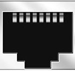 |
RJ45 | Konektor za LAN povezivanje |
| In1-14, In15-28 GND | Povezivanje upravljačkih uređaja (tipke, LED tipke, magnetni reed prekidači, detektori pokreta, senzori curenja, senzori temperature, itd.): In1 … In28 — logički ulazi GND — zajednički | |
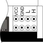 |
VCC GND L H |
Veza eksternih modula za CAN-bus VSS — 24V izlaz za napajanje eksternih uređaja GND — uobičajena L — CAN-L sabirnica podataka H — CAN-H sabirnica podataka |
| Indicator | Status | Description |
|---|---|---|
| Power | Power | |
| Power not available | ||
| Activity | Data communication | |
| Data communication not available | ||
| Error | No errors | |
| Communication error | ||
| Module overheat | ||
| Dimmer outputs module overload | ||
| Absence of power on dimmers, if in configuration |
Instalacija i montaža sistema
Prije povezivanja sistema morate:
- ugradite senzor i aktuatore (ako nisu prethodno instalirani), postavite senzore i aktuatore;
- lokacija modula i napajanja.
Napomena: Modul mora biti instaliran blizu izvora napona napajanja.
- Snaga sklopa prekidača mora biti u skladu sa kapacitetom opterećenja;
- Ništa drugo osim faznih provodnika se ne može spojiti na modul, neutralna žica se spaja zasebno.
Tipični dijagram povezivanja modula METAFORSA 3/3.plus prikazan je na 'sl. 3.

Priključak aktuatora
Priključak svjetla/električni kontaktor/termički aktuator grijanja
 Sl. 4 |
Takve aktuatore kao što su svjetlo, električni kontaktor, toplinski aktuator grijanja treba uključiti na bilo koji od izlaza 1 – 10, neutralnu žicu i žicu za uzemljenje spojiti direktno na razvodnu ploču. Primjer povezivanja je prikazan na Sl.4. |
Priključivanje uređaja visokog opterećenja
 |
Preporučeni kontaktori:
|
Priključak jednopolnog ventila za dovod vode/gasa
| Oprez: Prije uključivanja napajanja na opterećenje, provjerite je li konfiguracija izlaza METAFORSA modula ispravna. Neispravna konfiguracija ili neispravno povezivanje može uzrokovati kvar modula i/ili kvar opreme spojene na njega, pa čak i požar. | |
 Fig. 5 |
Jednopolni ventil za dovod vode/gasa spojen je na bilo koji od izlaza od 1 – 10, (neutralna žica i žica za uzemljenje spojeni su direktno na razvodnu ploču. Primjer povezivanja je prikazan na Sl. 5. |
Priključak dvopolnog ventila za dovod vode/gasa
| Oprez: Prije uključivanja struje na ventil, potrebno je osigurati ispravnu konfiguraciju izlaza METAFORSA modula. Neispravna konfiguracija može uzrokovati istovremeno dovođenje napona na oba kanala ventila, što može dovesti do kvara modula i/ili opreme spojene na njega, pa čak i do požara. | |
 Fig. 6 |
Dvije susjedne kontaktne točke (na primjer, 3, 4) koriste se za spajanje dvopolnog ventila za dovod vode/gasa; u ovim uslovima neutralna žica i žica za uzemljenje su spojene direktno na centralu. Primjer povezivanja je prikazan u Sl. 6. |
Priključak jednopolnog aktuatora kapije
| Oprez: Prije uključivanja napajanja na modul, trebate pravilno konfigurirati pristup aplikaciji. Neispravno konfigurisani kontakti mogu dovesti do kvara modula i/ili opreme koja je na njega povezana, pa čak i do požara.
| |
 Fig. 7 |
Bilo koja kontaktna točka (na primjer, 3) se koristi za povezivanje jednopolnih regulatora pogona kapije. Primjer povezivanja je prikazan na Sl.7. |
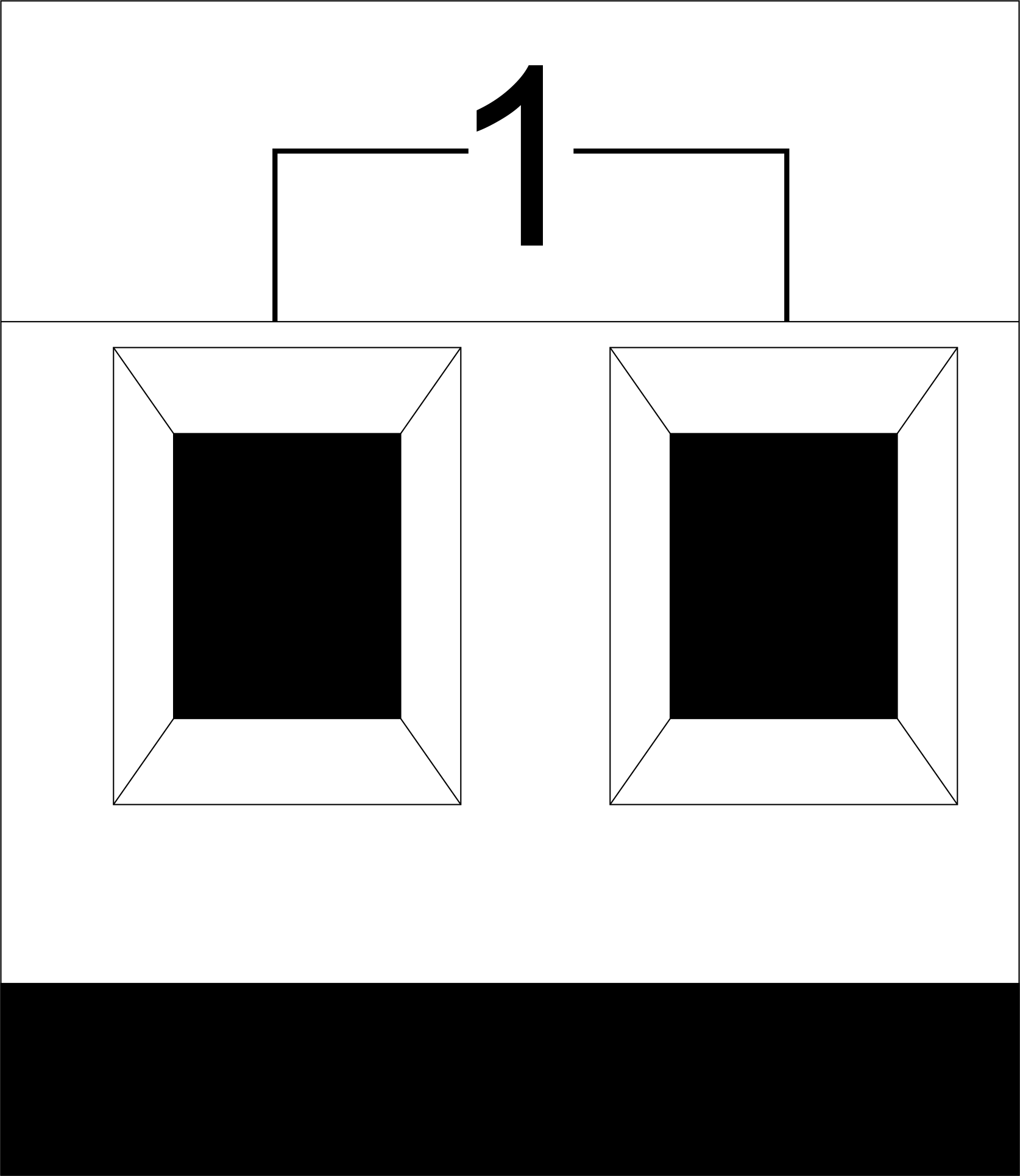
Priključak dvopolnog aktuatora kapije
| Oprez: Pre nego što primenite napajanje na modul, morate pravilno konfigurisati izlaze u aplikaciji. Neispravno konfigurisani kontakti mogu dovesti do istovremenog napajanja oba kanala, što rezultira kvarom modula i/ili kvarom opreme spojene na njega, pa čak i požarom.
| |
 Fig. 8 |
Dvije susjedne kontaktne točke (na primjer, 3, 4) treba da se koriste za povezivanje dvopolnog kontrolera pogona kapije. Primjer povezivanja je prikazan na Sl.8. |
Priključak aktuatora zavjese/žaluzije/zatvarača sa kontrolom sile od 220V
| Oprez: Pre nego što primenite napajanje na modul, morate pravilno konfigurisati izlaze u aplikaciji. Neispravno konfigurisani kontakti mogu dovesti do istovremenog napajanja oba kanala, što rezultira kvarom modula i/ili kvarom opreme spojene na njega, pa čak i požarom.
| |
 Fig. 9 |
Dve susedne kontaktne tačke (na primer, 3, 4) treba da se koriste za povezivanje aktuatora zavese/žaluzije/roladensa, u ovim uslovima neutralna žica i žica za uzemljenje su spojeni direktno na centralu. Primjer povezivanja je prikazan na Sl.9. |
Priključak aktuatora zavjese/žaluzije/zatvarača sa niskonaponskom kontrolom
| Oprez: Pre nego što primenite napajanje na modul, morate pravilno konfigurisati izlaze u aplikaciji. Neispravno konfigurisani kontakti mogu dovesti do istovremenog napajanja oba kanala, što rezultira kvarom modula i/ili kvarom opreme spojene na njega, pa čak i požarom.
| |
 Fig. 10 |
Dvije susjedne kontaktne točke (na primjer, 3, 4) treba koristiti za povezivanje aktuatora zavjesa/žaluzija/roladens sa niskonaponskom kontrolom. Primjer povezivanja je prikazan na Sl.10. |
Spajanje senzorskih elemenata/prekidača/dugmada
Connection of motion sensors/leakage sensors
The motion sensors/leakage sensors should be connected to any free input in1-in28; in these conditions their power is connected to the contact points of +5V and GND of the relevant group. The example of connection is shown in Fig.11.
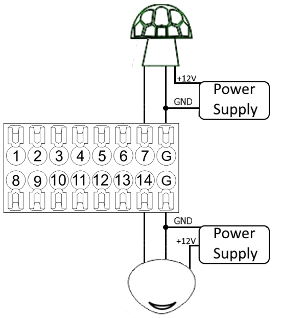
Fig. 11 connection of motion sensors/leakage sensors
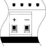
Connection of buttons/switches/magnetic reed switches
Buttons and reed switches are connected to any free input in1-in28, while their second contact point is connected to GND point of the relevant METAFORSA module group. The example of connection is shown in Fig. 12-13.
 Fig. 12 connection of buttons/switching units |
 Fig. 13 connection of the magnetic reed switches (window/door position sensors) |
Connection of temperature sensors
Temperature sensors are connected to any free input in1-in28, while their second contact point is connected to GND point of the relevant METAFORSA module group. The example of connection is shown in Fig. 14.
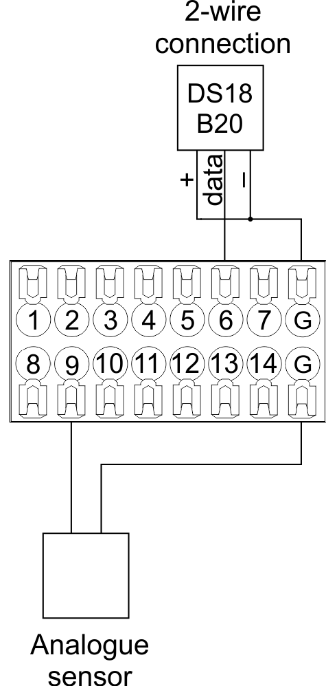
Fig. 14 connection of temperature sensors
RGB connection scheme
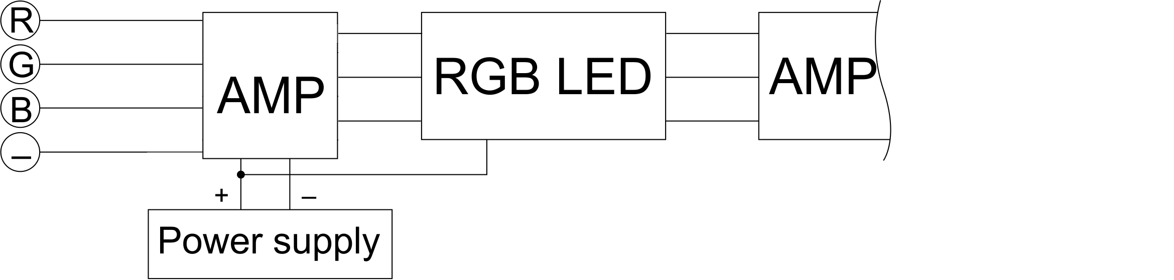
Fig. 15 RGB connection
WS2812B connection scheme

Fig. 16 WS2812B connection
RS485 connection scheme
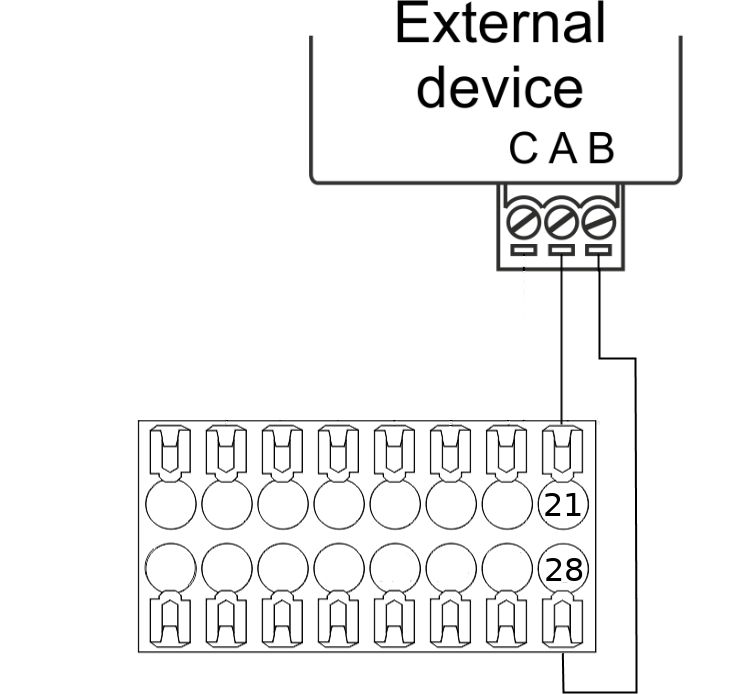
Fig. 17 RS485 connection
Connection of auxiliary equipment.
Expansion modules include Larnitech equipment connected through the CAN-bus. Such equipment includes: dimmers, RGB-backlit control modules, multimode sensors, etc. The equipment connected to the expansion port is defined automatically and does not require any preset tuning. Connector contact pin assignment is defined in Table 4. The example of connection is shown in Fig. 18.

|
| Caution! The 120 ohm terminating resistors should be installed at the end connectors between L and H contact points of CAN-bus. Ensure the connection is correct. The incorrect connection may cause sensor and/or module malfunction. |
Module installation and connection procedure
- Install the module in the switchboard on the DIN-rail and fix it with the special latch on the module base.
- Fasten the supply unit on the left side of the module.
- Connect the connector (4) having the noise filter pre-installed which is supplied complete with the module.
- Connect the connectors (5), (6).
- Connect the connectors (1), (2).
- Connect the connector (3).
- Apply power to the supply unit of METAFORSA module.
- Wait until the module is loaded, then configure it in accordance with the System Setup Instructions.
- Apply power to the connectors (1), (2).
- Check all equipment for proper operation.
METAFORSA module shut-off and deinstallation procedure
- De-energize the module by disconnecting the circuit breaker assembly of the load power supply and METAFORSA module supply unit. Verify the voltage is absent on the terminals (1), (2) of the connector wires and on the input terminals of the supply unit.
- Disconnect the load power supply connectors (1), (2).
- Disconnect the connector (3).
- Disconnect the connectors (4)-(6).
- Remove the module from the DIN-rail, releasing the latch at the bottom of the module base.
Hardware setup
To configure and control METAFORSA SMART HOUSE, you must install Larnitech software on your smartphone or tablet, which is available in App Store and Play Market. After installation, follow the System Setup Instructions.
Fault diagnostics and handling
The following are some possible faults and ways of fault handling. If you have any difficulty, or face the fault undeclared here, please contact the Technical Support: [1] or [support@larnitech.com]. There are also some tips in the FAQ section at our website [2].
The actuators do not operate:
- ensure the outputs are properly configured in the application (see System Setup Instructions);
- check the connection is correct in accordance with table 2 and paragraph 3.6;
- ensure the power is supplied to the input power contact , i.e. all circuit breaker assembly are ON.
- verify the operability of the connected equipment.
The module is off, indication absent:
- check the connection to 24V supply unit as shown in table 2 (contacts pin assignment);
- check the connection of the supply unit to 220V power mains, the indicator should be ON.
Network connection fault:
- ensure the Ethernet cable is properly wired and connected to the connector;
- ensure the LED status indicators are ON on the Ethernet connector;
- check the LAN configuration is correct, Ethernet cable loops are absent;
- METAFORSA module and the device you are connecting from are in the same network.
hold integer 0-10000 1-10 by default hold is the same as runtime hold is the bridging time in miliseconds, is used for gate and jalousie, lock; Example: hold=3500
The sensors do not operate:
- ensure the inputs are properly configured in the application (System Setup Instructions);
- check the connection is correct in accordance with table 2 and paragraph 3.7;
- ensure the METAFORSA module is ON: circuit breaker assembly is closed, indication on the supply unit is ON, the module indication corresponds to the operating status – table 3;
- check the power supply availability on the sensors;
- check the integrity of lines laid to the sensors.
The auxiliary equipment does not operate:
- check the connection is correct in accordance with table 2 and paragraph 3.8-9;
- ensure the METAFORSA module is ON: circuit breaker assembly is closed, indication on the supply unit is ON, the module indication corresponds to the operating status – table 3;
- check the integrity of the CAN lines, voltage supply on the modules.
HW Settings
| Name | Type, range | SUBID | Default | Description |
|---|---|---|---|---|
| runtime | integer 0-100 | 1-10 | 15 | runtime is the open/close time in seconds, is used for jalousie, gate, valve(2 pole);
|
| runtimeopen | integer 0-60000 | Blinds subId | Runtimeopen is the open time in milliseconds, is used for blinds; Example: runtimeopen=15000 | |
| runtimeclose | integer 0-60000 | Blinds subId | Runtimeclose is the close time in milliseconds, is used for blinds; Example: runtimeclose=15000 | |
| hold | integer 0-10000 | 1-10 | 500 | hold is the bridging time in milliseconds, is used for gate and jalousie (by default hold is the same as runtime for jalousie and gate), lock; Example: hold=3500 |
| def | string 'ON' | 1-10 | 'OFF' | def is the element status is set after restart, is used for lamp, heating, valve(1 pole); Example: def='ON' |
| stop | Char ‘R’ | 1-7 | – | (for 2-pole gate and blinds) If it is declared then by Stop command during the motion, the same impulse appears as it was at the beginning of the motion. Pole, an which the stop-impules is formed, is defined by the parameter Stop value. If it is ‘r’ or ‘R’ then stop-impulse is produced on the opposite to the start-impulse pole. If any other value is delcared (e.g., ‘d’ ) then the stop-impulse is on the same pole. If a Runtime passed after the beginning of the motion then the stop-impulse is not formed. Example: stop=’r’ |
| out | char[10] | 98 | 'LLLLHHHHP-' | Each char is responsible for the type of a particular channel
Example: out='LLB-G-V-W-' |
| dm | char[4] | 98 | ‘LLLL’ | Each char is responsible for the type of a particular channel
Example: dm=’skl-‘ |
| def | integer 0-250 | 11-14 | 100 | The default brightness level in case of a power reset (1..250). Example: def=250 |
| min | integer 0-100 | 11-14 | 0 | Minimum dimming level, example: min=10 |
| max | integer 0-100 | 11-14 | 100 | Maximum dimming level, example max=95 |
| start | integer 0-100 | 11-14 | 0 | The Start function is used for lamps that lack the minimal voltage to get turned on. If the set value is lower than the start value, the lamp is turned on at the start value and them the light is dimmed down to the set level. Example: start=60 |
| force | integer 0-100 | 11-14 | 10 | Time duration of the starting value (measured in milliseconds). Example: force=20 |
| runtime | integer 0-60000 | 11-14 | 1000 | Runtime is the speed of changing the brightness from ‘min’ to ‘max’ (measured in milliseconds). Example: runtime=1000 |
| offset | integer (+/- 0…39) | 39-46 | '0' | sensor values offset; For example, offset is -3.8 :
Example: hw="offset='-3.8'" |
| io | char[28] | 98 | io='KKKKKKKKKKKKKKKKKKKKKKKKKKKK' | Each char is responsible for the type of a particular channel
Example: io='KKKKKKKKKKKKKKKKKKKKKKKKKKKK' |
| hw | string | 98 | - | hw="...", where
Example: 1hw="io='4---zdd----t--' pwm_invert=1 lbn_bright=255 f=1000"
|
| Only for Metaforsa 3.plus | ||||
| cfg | string | 98 | 9600/8N1 | cfg='SPEED/BPS', where
Example: 1hw="cfg='9600/8N1'"
|
| [Protocol] | string | 98 | — | Protocol setting is described by protocol parameter. The following
protocols are supported:
Example: 1hw="cfg='9600/8N1' modbus"
|
| echo | on; off | 98 | 'off' | For settings check out and testing echo parameter can be used. Module
echo-reply can be turned on or off with the help of this parameter.Echo parameter value:
Example: 1hw="cfg='9600/8N1' echo='off'"
|
 1		<item addr="349:1" auto-period="600" cfgid="197" name="Lamp 1" type="lamp"/>
 2		<item addr="349:2" auto-period="600" cfgid="197" name="Lamp 2" type="lamp"/>
 3		<item addr="349:3" auto-period="600" cfgid="197" name="Lamp 3" type="lamp"/>
 4		<item addr="349:4" auto-period="600" cfgid="197" name="Lamp 4" type="lamp"/>
 5		<item addr="349:5" auto-period="600" cfgid="197" name="Lamp 5" type="lamp"/>
 6		<item addr="349:6" cfgid="197" name="Radiator" temperature-lag="0.2" type="valve-heating">
 7			<automation name="Eco" temperature-level="16"/>
 8			<automation name="Comfort" temperature-level="22"/>
 9			<automation name="Hot" temperature-level="25"/>
10		</item>
11		<item addr="349:7" cfgid="197" name="Radiator" temperature-lag="0.2" type="valve-heating">
12			<automation name="Eco" temperature-level="16"/>
13			<automation name="Comfort" temperature-level="22"/>
14			<automation name="Hot" temperature-level="25"/>
15		</item>
16		<item addr="349:8" cfgid="197" name="Radiator" temperature-lag="0.2" type="valve-heating">
17			<automation name="Eco" temperature-level="16"/>
18			<automation name="Comfort" temperature-level="22"/>
19			<automation name="Hot" temperature-level="25"/>
20		</item>
21		<item addr="349:9" cfgid="197" name="Jalousie" sub-type="120" type="jalousie"/>
22		<item addr="349:11" auto-period="600" cfgid="197" name="Dimmer 1" type="dimmer-lamp"/>
23		<item addr="349:12" auto-period="600" cfgid="197" name="Dimmer 2" type="dimmer-lamp"/>
24		<item addr="349:13" auto-period="600" cfgid="197" name="Dimmer 3" type="dimmer-lamp"/>
25		<item addr="349:14" auto-period="600" cfgid="197" name="Dimmer 4" type="dimmer-lamp"/>
26		<item addr="349:16" cfgid="197" name="Door 1" type="door-sensor"/>
27		<item addr="349:17" cfgid="197" name="Door 2" type="door-sensor"/>
28		<item addr="349:18" cfgid="197" name="Door 3" type="door-sensor"/>
29		<item addr="349:19" cfgid="197" name="Door 4" type="door-sensor"/>
30		<item addr="349:20" cfgid="197" name="Door 5" type="door-sensor"/>
31		<item addr="349:21" cfgid="197" name="Door 6" type="door-sensor"/>
32		<item addr="349:22" cfgid="197" name="Door 7" type="door-sensor"/>
33		<item addr="349:23" cfgid="197" name="Door 8" type="door-sensor"/>
34		<item addr="349:24" cfgid="197" name="Door 9" type="door-sensor"/>
35		<item addr="349:25" cfgid="197" name="Door 10" type="door-sensor"/>
36		<item addr="349:26" cfgid="197" name="Door 11" type="door-sensor"/>
37		<item addr="349:27" cfgid="197" name="Door 12" type="door-sensor"/>
38		<item addr="349:28" cfgid="197" name="Door 13" type="door-sensor"/>
39		<item addr="349:29" cfgid="197" name="Door 14" type="door-sensor"/>
40		<item addr="349:30" cfgid="197" name="Door 15" type="door-sensor"/>
41		<item addr="349:31" cfgid="197" name="Door 16" type="door-sensor"/>
42		<item addr="349:32" cfgid="197" name="Door 17" type="door-sensor"/>
43		<item addr="349:33" cfgid="197" name="Door 18" type="door-sensor"/>
44		<item addr="349:34" cfgid="197" name="Door 19" type="door-sensor"/>
45		<item addr="349:35" cfgid="197" name="Door 20" type="door-sensor"/>
46		<item addr="349:36" cfgid="197" name="Door 21" type="door-sensor"/>
47		<item addr="349:37" cfgid="197" name="Door 22" type="door-sensor"/>
48		<item addr="349:38" cfgid="197" name="Door 23" type="door-sensor"/>
49		<item addr="349:39" cfgid="197" name="Door 24" type="door-sensor"/>
50		<item addr="349:40" cfgid="197" name="Door 24" type="door-sensor"/>
51		<item addr="349:41" cfgid="197" name="Door 25" type="door-sensor"/>
52		<item addr="349:43" cfgid="197" name="IR receiver" type="ir-receiver"/>
53		<item addr="349:44" cfgid="197" name="RS485" type="com-port"/>
54		<item addr="349:90" cfgid="197" name="Current" system="yes" type="current-sensor"/>
55		<item addr="349:95" cfgid="197" name="Temperature" system="yes" type="temperature-sensor"/>
56		<item addr="349:96" cfgid="197" name="Temperature" system="yes" type="temperature-sensor"/>
57		<item addr="349:97" cfgid="197" name="Temperature" system="yes" type="temperature-sensor"/>
58		<item addr="349:98" cfgid="197" hw="out='LLLLLHHHB-' dm='LLLL' io='KKKKKKKKKKKKKKKKKKKKUKKKKKK-'" logic-ver="19" name="Temperature" sn="2533726919" system="yes" type="temperature-sensor"/>
59		<item addr="349:100" cfgid="197" name="RS232" type="com-port"/>